Alternator Repair CS-130
GENERAL INFORMATION
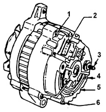
Generator through bolts
1. THROUGH BOLT (3 PCS.).
2. S. F. L. TERMINAL BLOCK.
3. "BAT" TERMINAL LEAD.
4. RIVET.
5. COVER.
6. RIVET.
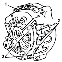
Generator rear cover
1. REMOVE 3 PINS.
2. DISCONNECT THE STATOR WIRE CONNECTIONS FROM THE RECTIFIER BLOCK.
3. REMOVE THE RIVETS.
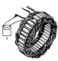
Generator stator check with OHMMETER (CHECK FOR GROUND/"BODY" SHORT)
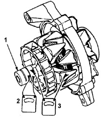
Generator armature check
1. BEARING.
2. OHMMETER (CHECK FOR SHORT CIRCUIT AND GROUND).
3. OHMMETER (CHECK FOR GROUND).
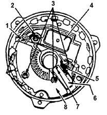
Removing the brush holder, voltage regulator and rectifier block
1. WELDED CONNECTION.
2. "BAT" TERMINAL LEAD.
3. SCREW.
4. VOLTAGE REGULATOR.
5. WELDED CONNECTION.
6. BRUSH HOLDER.
7. BRUSH HOLDER MOUNTING PIN.
8. RECTIFIER BLOCK.
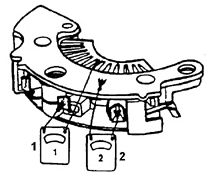
Rectifier block check
1. OHMMETER.
2. OHMMETER.
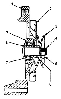
Generator front bearing
1. FRONT COVER.
2. FAN.
3. PULLEY.
4. SHAFT.
5. NUT.
6. SPACER SLEEVE.
7. RING.
8. RING.
9. SEALED BEARING.

Generator rear bearing
1. BEARING MOUNTING SEAT.
PROCEDURE.
1. Make alignment marks across the covers and the generator stator to simplify generator reassembly.
2. Unscrew the 3 through bolts and remove the rear cover.
3. Remove the rivet or pin and remove the slip ring cover.
4. Unsolder and disconnect the stator wires from the rectifier block terminals. To avoid damaging the rectifier diodes, avoid overheating the wires and terminals with the soldering iron.
Warning.
If the stator wires are welded to the rectifier block terminals, it is necessary to
cut the wires.
5. Remove the stator.
6. Remove the deflector washer from the rear cover cavity by removing the 3 pins.
7. Check the stator windings for ground with an ohmmeter. Replace the stator if the windings are faulty.
8. Check the armature windings for ground with an ohmmeter (the front cover remains installed). If a short to ground is present, replace the armature. To loosen the shaft nut, first secure the shaft.
9. Check the armature windings for short circuit and ground.
The winding resistance must be within 1.7–2.3 Ohm. Otherwise,
replace the armature.
10. Unscrew the screw and remove the brush holder. Check the condition of the brushes. If the brushes are serviceable, wipe them with a clean, soft cloth and insert them into the
brush holder.
11. Remove the terminal lead located between the voltage regulator and the
rectifier block and remove them from the generator rear cover.
12. Check the rectifier block by connecting the ohmmeter to the stator phase winding terminal and the air-cooled diode heatsink. Repeat the check with the ohmmeter leads reversed.
If the ohmmeter readings are the same in both cases, replace the
rectifier block. Check the two remaining diode circuits in the same way.
rectifier.
Warning.
Some types of digital ohmmeters are not suitable for checking diodes. In this
case, consult the manufacturer's representative about
the possibility of checking the rectifier block condition.
13. Check the three diodes in sequence by connecting the ohmmeter to the stator phase
winding and the base plate. If the ohmmeter readings do not change when the
ohmmeter leads are reversed, replace the rectifier block.
14. During assembly, tighten the nut to 54–108 N·m while holding the shaft against rotation.
15. Install a new ring in the generator rear cover.
16. Press the new bearing into the rear cover seat until it bottoms out and secure it.
17. Install the brush holder on the rear cover and secure it with the
insulated screw. Position the brush holder so that the brushes are
perpendicular to the rectifier block, then secure the brush holder with the
pin.
18. Apply a layer of sealant to the mating surfaces of the rectifier block and rear cover (for better heat transfer and diode cooling) and install the rectifier block on the cover. After installing the brush holder and the rectifier block, make the welded connections.
19. Secure and weld the voltage regulator and the rectifier block together.
Block..
20. Secure the new reflector washer with a pin.
21. Install the stator and weld 3 wires to the phase winding terminals.
of the rectifier block. Avoid overheating the diodes during welding.
22. Install and secure the outer cover with pins..
23. Install the slip rings by pressing the outer and inner rings onto the shaft.
and connect the front cover with the pulley to the armature.
When pressing on the rings, make sure the clearance between the outer ring and the rear cover is within 1.9–2.2 mm..
24. Install the 3 tie bolts and remove the brush retaining pin.
Test yourself
A quick Daewoo Nexia quiz: every answer comes with an explanation and a link to the manual page.