Repair of 5MT and 10MT starter components
GENERAL INFORMATION

Starter parts
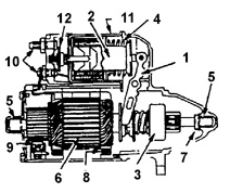
Starter assembly (longitudinal section)
1. DRIVE LEVER.
2. PULL-IN RELAY ARMATURE
3. OVERRUNNING CLUTCH
4. ARMATURE RETURN SPRING
5. BUSHING
6. MOTOR ARMATURE
7. PINION STOP
8. FIELD WINDING (STATOR)
9. BRUSH
10. PULL-IN RELAY TERMINALS
11. PULL-IN RELAY HOUSING
12. CONTACT DISC
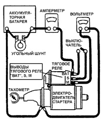
Disassembly, inspection and assembly of starter

Starter installation on engine A. WIRE TERMINAL MOUNTING STUDS
20. WASHER
21. STARTER
22. LOWER BOLT
23. UPPER BOLT
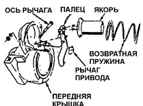
Drive lever and pull-in relay armature

Pinion and overrunning clutch
1. ARMATURE SHAFT
2. THRUST WASHER
3. SNAP RING
4. BUSHING
5. OVERRUNNING CLUTCH AND PINION ASSEMBLY
6. FIBER WASHER
7. CENTER BEARING
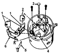
Replacement of brush holder, standard starter
1. BRUSH HOLDER (INSULATED)
2. BRUSH
3. BRUSH HOLDER PIN
4. BRUSH HOLDER BRACKET
5. BRUSH HOLDER SPRING
6. BRUSH HOLDER (NON-INSULATED)
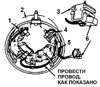
Replacement of brush holder, lower output 5MT starter
1. BRUSH HOLDER PLATE
2. STATOR WINDING HOUSING
3. BRUSH HOLDER PLATE
4. BRUSH HOLDER
5. RIVET
6. BRUSH
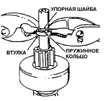
Installation of bushing, thrust washer and snap ring

Checking pinion axial clearance
Checking
After removing the starter from the engine, check the freedom of movement of the
pinion along the helical spline of the shaft and the freedom of rotation of the motor shaft (using a screwdriver).
If the shaft binds, disassemble the starter immediately. If the shaft rotates normally, first test the starter under no-load conditions, then disassemble it if necessary.
Assemble the test circuit for the starter as shown in the figure. Disassembly,
inspection and assembly of starter. Switch on the starter and measure the current consumption,
voltage and motor shaft speed. Compare the obtained values
with the rated values.
If the rated values are given without the current consumed by the pull-in relay,
correct the measurement results by subtracting the rated current consumed by the hold-in winding of the relay.
Switch off the power and disassemble the test circuit.
1. If the current consumption and motor shaft speed correspond to the rated values, the starter is serviceable.
2. Low shaft speed and high current consumption indicate the following faults:
– increased resistance to rotation due to excessive interference fit, wear or
contamination of bearings, bending of motor armature, etc.
– short circuit in armature windings.
– short circuit in armature windings or field windings.
3. If the shaft does not rotate with high current consumption, possible causes
are:
– ground fault in field winding or at terminals.
– seized bearings (check by rotating the armature by hand). Disassemble the starter.
4. If the shaft does not rotate with no current in the circuit, possible causes
are.
– open circuit in the field winding. Disassemble the starter and check the internal
commutator and winding continuity using a test lamp.
– open circuit in the armature winding. Disassemble the starter and inspect the armature.
– broken brush spring, worn brushes, contaminated commutator segments, or other causes of poor brush contact with the commutator segments. Disassemble the starter.
5. Low armature shaft speed with low current draw.
– increased internal resistance due to poor connections or faults in the
wires, contaminated commutator segments, or other causes. Disassemble the starter.
6. High no-load speed with high current draw.
usually indicates a short circuit in the field winding. Disassemble the
starter and check the stator field windings.
Disassembly.
PROCEDURE.
1. Remove the terminal and starter relay mounting screws. Turn the relay housing 90 degrees and remove it together with the armature and spring. Check and repair the relay.
2. Remove the two through-bolts, then remove the rear cover and washer. (On starters for diesel vehicles, also remove the insulating gasket.)
3. Separate the stator housing from the front cover. (On starters for diesel vehicles, the motor armature remains in the front cover.) Operation
is performed only on starters intended for diesel vehicles.
4. Remove the shift lever pivot shaft. This operation is performed only on starters
intended for diesel vehicles.
5. Remove the motor armature from the front cover bushing. After this, the shift lever and relay armature can be removed freely (see figure Drive Lever and Relay Armature).
6. If necessary, remove the overrunning clutch (OWC) from the armature shaft. Perform the following
operations (see figure Pinion and Clutch Assembly):
6a. Remove the thrust washer.
6b. Place a long tip about 16 mm in diameter or a suitable length of tube on the shaft and against bushing 4. Tap the tube lightly to remove the bushing from the snap ring.
6c. Remove the snap ring from the groove on the shaft. If the ring is deformed, replace it with a new one during reassembly.
6d. Remove the bushing and overrunning clutch from the armature shaft. (On stator for diesel vehicles,
additionally remove the fiber washer and center bearing from the shaft.)
7. Remove the pin, then remove the drive lever and relay armature.
8. If necessary, remove the brush holder on a standard starter.
perform the following operations (see figure Brush Holder Replacement, standard
starter):
8a. Remove the brush holder pivot pin.
8b. Remove the brush holder spring.
8c. Replace brushes if necessary.
9. If necessary, remove the brush holder on the 5MT starter, perform
the following operations (see figure Brush Holder Replacement, 5MT starter of lower
power):
9a. Remove the brush holder from the bracket.
9b. Remove the screw from the brush holder and remove the brush.
9c. Check the brush holder for serviceability and absence of damage or wear.
9d. If necessary, replace the brushes and/or brush holders.
Assembly.
PROCEDURE.
1. Install the overrunning clutch with pinion on the armature:
1a. Lubricate the end of the armature shaft with grease 1960954 or equivalent.
1b. Install the center bearing on the shaft (starters for diesel vehicles). The bearing must face the armature winding. Then install the fiber washer on the shaft.
1c. Install the overrunning clutch with pinion on the shaft. The pinion must be located closer to the end of the shaft.
1d. Install the bushing on the armature shaft. The groove in the bushing must face the end of the shaft.
1e. Install the snap ring in the groove of the armature shaft.
1f. Install the thrust washer on the shaft.
1g. Position the bushing and thrust washer on opposite sides of the snap ring. Using two pliers, compress the bushing and snap ring and press the snap ring into the bushing. The bushing must be securely retained axially on the armature shaft.
snap ring into the bushing. The bushing must be securely retained axially on the armature shaft..
2. Lubricate the starter front cover bushing with grease 1960954 or equivalent.
3. Insert the end of the drive lever into the annular groove of the overrunning clutch bushing and install the clutch in the starter front cover. On starters for vehicles with gasoline
engines, the drive lever may be installed beforehand.
4. Insert the drive lever pivot shaft and secure it.
5. Install the starter relay assembly and the lever pin.
6. Apply a layer of sealant N 1050026 or equivalent to the mating
surface of the relay that contacts the stator housing.
7. Attach the stator housing to the front cover, locating it on the guide pin. Take care not to damage the brushes.
8. Lubricate the starter rear cover bushing with grease 1960954 or equivalent.
9. Install the washer on the rear end of the armature shaft, fit the rear cover, then install and
tighten the through-bolts into the through holes. On starters for diesel vehicles,
install an insulating gasket before fitting the rear cover.
When installing the through-bolts, make sure they pass through the
holes in the gasket.
10. Connect the stator winding wire to the starter relay terminals. When assembling
the starter or after replacing the starter relay, check the pinion axial clearance.
Correct pinion clearance is required to prevent friction of the shift
fork lever against the overrunning clutch bushing when the starter motor is running.
11. Disconnect the stator winding wire from the starter relay terminal and insulate the wire thoroughly.
Insulate the wire.
12. Connect one wire from the battery to the starter relay winding terminal,
and the other to the stator.
13. Briefly connect the relay terminal to the stator with a jumper wire. The pinion must extend forward into the working
position and remain there until the battery is disconnected.
14. Move the pinion back, fully taking up the axial clearance. Measure the pinion axial clearance with a feeler gauge. The pinion axial clearance must be within 0.25–3.5 mm. The starter design does not provide
for adjustment of the pinion axial clearance. If the clearance is outside the permissible range, check the starter assembly and replace worn parts.
Test yourself
A quick Daewoo Nexia quiz: every answer comes with an explanation and a link to the manual page.