Alternator Troubleshooting CS-121
GENERAL INFORMATION

Wiring diagram for alternator check on vehicle
1. CARBON SHUNT.
2. VOLTMETER.
3. RESISTOR.
4. AMMETER.
5. ALTERNATOR.
6. BATTERY.
7. RESISTANCE AT POSITIVE LEAD TERMINAL
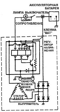
Alternator wiring diagram
With a serviceable alternator, the battery discharge warning light should come on when
the ignition is switched on and go out after the engine starts. If the warning light indicates
abnormal alternator operation or the battery is not charging, troubleshoot the fault. Also note that often
the battery discharge is caused by prolonged use of electrical consumers
with the engine off. One possible cause of discharge may be
a faulty switch for a lamp, for example the trunk or glove box lamp. In this case, when the lids are closed, the lamps do not switch off but remain
on and discharge the battery..
1) Visually check the condition of the belt and wires..
2) With the ignition on and engine not running, the warning light should
illuminate. If it does not, disconnect the electrical leads from the alternator and connect
terminal L lead to ground through a jumper wire with a 5 A fuse.
5 A..
2a. If the warning light comes on, replace the alternator..
2b. If the warning light still does not come on, there is an open circuit in the wiring from the ignition switch to the
lead terminal. The warning light bulb may also be burnt out. 3) With the ignition on and engine running at low idle speed, the warning light should be off. If it is on, disconnect the electrical
leads from the alternator..
leads from the alternator..
3a. If the warning light goes out, replace the alternator..
3b. If the warning light stays on, there is a short to ground in the circuit from the lead terminal to the
warning light..
Warning.
Check alternator operation per step 4 before concluding that the voltage regulator has failed..
4) Check alternator operation..
Warning.
For an accurate check, the battery must be
fully charged..
4a. Assemble the circuit shown in Fig. Wiring diagram for alternator check on vehicle. Make sure the carbon shunt is off.
4b. With ignition off, measure and record the battery voltage..
4c. Disconnect the lead terminals from the alternator..
4d. Turn on the ignition (engine must not run) and measure the voltage at the L lead terminal with a digital tester.
This voltage should be approximately equal to
the battery terminal voltage. If the voltage at terminal L differs significantly from the battery voltage, check the wiring from the warning light to
terminal L for an open circuit or short to ground. Repair any detected
faults..
4e. Connect the leads to the alternator..
4f. Start the engine and measure the battery terminal voltage at low crankshaft speed. This voltage should be higher than the voltage measured in step 4d but must not exceed 16 V. Otherwise
replace the alternator..
4g. Measure alternator current at low engine speed at idle.
Using the carbon shunt adjustment, achieve
maximum alternator current with battery terminal voltage not
less than 13 V. If the measured current differs from the rated value by no more than
15 A, the alternator is serviceable. Otherwise, replace the alternator. 4h. With the alternator operating at maximum output, measure with a voltmeter
the voltage between the alternator housing and the battery negative terminal. Voltage drop must not exceed 0.5 V. If the voltage drop exceeds 0.5 V, check the circuit between the alternator housing and the battery and identify the
cause. Clean and tighten the wire connections to ground.
Test yourself
A quick Daewoo Nexia quiz: every answer comes with an explanation and a link to the manual page.