Crankshaft - Inspection
1. Inspect the crankshaft main and connecting rod journals for damage (scoring and seizure), excessive wear, and cracks. Also inspect the oil passages for blockage. Repair or replace any defective part.
2. Inspect the taper and out-of-round of the crankshaft main and connecting rod journals.
Main journal diameter: 57 mm Connecting rod journal diameter: 45 mm Taper and out-of-round of main and connecting rod journals:
0.01 mm or less Standard value:
MAIN AND CONNECTING ROD BEARING INSERTS
Visually inspect the surface of each bearing insert (flaking, uneven contact, scratches, scoring, etc.). Replace any defective bearing inserts.
BEARING CLEARANCE MEASUREMENT
1. Measure the diameter of the crankshaft main and connecting rod journals.
2. Measure the inside diameters of the main bearing bores (in the cylinder block and bearing cap) and the connecting rod bearing bores (in the connecting rod big end and connecting rod cap).
3. Measure the thickness of the connecting rod and main bearing inserts.
4. Calculate the bearing clearance from the measurements (subtract the journal diameter and the bearing insert thickness from the inside diameter of the bearing bore).
Main bearing clearance:
0.028 - 0.048 mm Connecting rod bearing clearance: (Specified limit for new parts) 0.024 - 0.044 mm
OIL SEAL Inspect the front and rear crankshaft oil seals for damage or wear of the sealing lips. If any defects are found, replace the oil seal.
BEARING CAPS
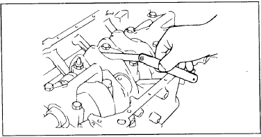
After installing the main bearing caps, check that the crankshaft rotates smoothly and that the crankshaft end play is within the standard value. If the end play exceeds the specified limit, replace the thrust half-washers and/or the bearing inserts.
Standard value: 0.06 - 0.26 mm Specified limit: 0.30 mm
CRANKSHAFT POSITION SENSOR ROTOR
1. Remove the crankshaft position sensor rotor.
2. Inspect the crankshaft position sensor rotor for damage, cracks, and wear. If necessary, replace the sensor rotor.
3. Check the clearance between the sensor rotor tooth and the sensor tip using a depth gauge.
Standard value:
Clearance between crankshaft position sensor rotor tooth and sensor tip: 0.5 – 1.1 mm
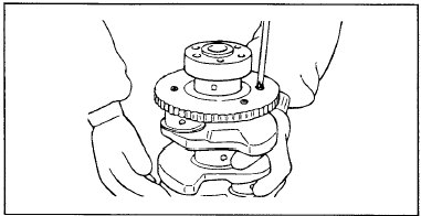
• Measure the distance from the tip of the crankshaft position sensor rotor tooth to the sensor mounting surface on the cylinder block.
• Measure the length of the crankshaft position sensor tip as the distance between the end of the sensor tip and the sensor mounting surface.
• Calculate the clearance as the difference between the specified values.
Test yourself
A quick Hyundai Elantra CN7 quiz: every answer comes with an explanation and a link to the manual page.