The Power Liftgate (PTL) system automatically opens and closes the vehicle's liftgate and stops the liftgate at a specified position. The liftgate can be operated using the internal switches (instrument panel switch, liftgate interior switch, liftgate exterior handle switch) and the remote transmitter. The Power Trunk Module (PTM) transmits and receives vehicle information via CAN communication with the ECU to determine the liftgate position (open or closed) and perform self-diagnosis. Liftgate position and direction: The PTL system measures the position of the connecting line using the built-in Hall sensor inside the drive motor. The liftgate movement direction is detected by analyzing the current direction of the motor. Hall sensor counting (position detection) is active in power mode and in manual mode. Drive motor power control: Drive motor power is regulated by PWM (pulse width modulation) at 20 kHz. Depending on the expected and actual speed of the liftgate, the ECU regulates motor power to achieve the required opening and closing speed. Liftgate speed control: To control liftgate speed while compensating for aging, temperature effects and vehicle inclination, the adjustment is included. The regulation compares the actual motor speed with the required motor speed. Depending on the result of the comparison, the speed is adjusted by increasing or decreasing motor power. System components
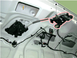
Power Liftgate (PTL) Actuator (A).Installed inside the left side trim of the luggage compartment, it opens and closes the liftgate. The motor is connected to the push rod through a gear. It consists of an ECU and an actuator. The actuator consists of an actuator bracket, gear motor, push rod and actuator arm.
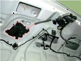
Power Latch Assembly (A)It sends open/close signals for the liftgate to the power trunk module actuator. It consists of a power latch and an actuating mechanism.
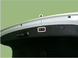
Latch Actuator (A)Using the built-in motor, the power latch is pulled by the Power Trunk Module control unit to perform latching in step 1/2.
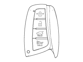
Latch Actuator (A)To open or close, press the power trunk module button (A) on the wireless transmitter for more than one second. If the button is pressed again while the liftgate is closing, liftgate operation stops.
Liftgate Interior Switch (A)It is installed in the liftgate interior trim and cannot be operated when the liftgate is closed. If the lock switch is turned on, the PTM sends a liftgate lock signal to the SMK. After receiving the signal, the SMK uses the bumper antenna to authenticate the FOB. If a registered key FOB is detected, its search continues in the interior area. If all doors are closed and there is no FOB inside, the SMK sends a door lock command to the DDM and a liftgate close command to the PTM. The DDM and PTM execute the command, the door locks and the liftgate closes.
Buzzer
Liftgate Glove Box Switch (in glove box)It is installed in the glove box on the passenger side. It is used to control LOCK/UNLOCK operation of the liftgate.
Operation
Power Trunk Open/Close Flow
Open Flow
Open Step
Description
1
Press the liftgate exterior handle
2
Ignition ON > SJB (Smart Junction Box) receives switch signal
3
The SJB sends an open signal to the PTM via CAN communication.
4
The PTM sends an unlock output signal to the power latch unit.
5
PTM operates drive motor > Sector gear operation (rotation) > Push rod operation (open)
6
Liftgate open
Close Flow
Open Step
Description
1
Press the liftgate interior close switch
2
PTM operates drive motor > Sector gear operation (rotation) > Push rod operation (closed)
3
Power latch step 1 (close) > Latch drive motor operation (rotation)
4
Latch drive cable control > Power latch, step 2
5
Close Liftgate
?
Test yourself
A quick Hyundai Genesis DH quiz: every answer comes with an explanation and a link to the manual page.