Front Driveshaft
Components and Component Location
Component Location
[Gamma 1.6 MPI, Nu 2.0 MPI, New U 1.6 CRDi]
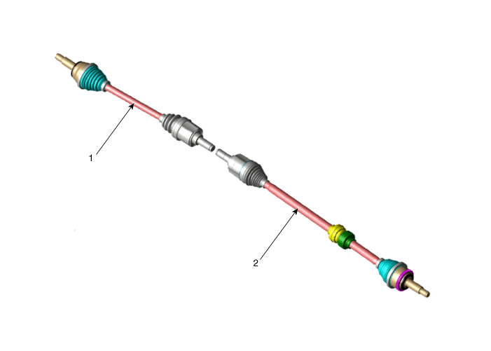
| 1. Drive shaft (LH) | 2. Drive Shaft (RH) |
[Gamma 1.6 T-GDI]
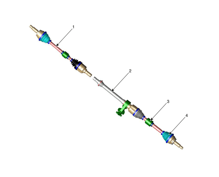
| 1. Drive shaft (LH) 2. Inner shaft bearing bracket |
3. Dynamic damper 4. Driveshaft (right) |
[RH]
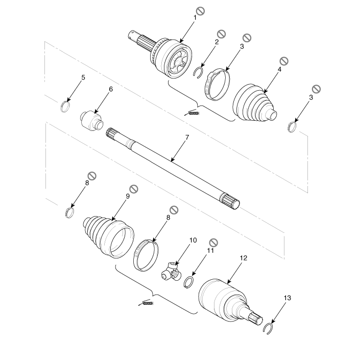
| 1. BJ assembly 2. Clip 3. BJ boot band 4. Boot |
5. Dynamic Damper Band 6. Dynamic Damper 7. Shaft 8. TJ Boot Band |
9. TJ Boot 10. Spider Assembly 11. Snap Ring 12. TJ Housing |
13. Snap ring |
[LH]
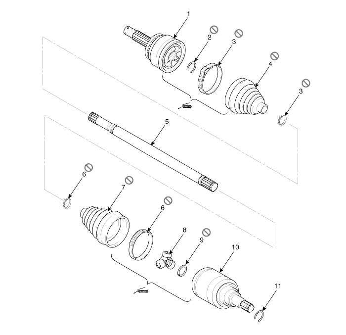
| 1. BJ Assembly 2. BJ Snap Ring 3. BJ Boot Band 4. BJ Boot |
5. Shaft 6. TJ Boot Band 7. TJ Boot 8. Spider Assembly |
9. Retaining ring 10. TJ housing 11. Snap ring |
Repair Procedures
Removal and Installation
Drive Shaft
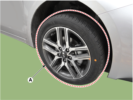
Remove the front wheel and tire (A).
Tightening torque: 107.9–128 N·m
Disconnect the tie rod end ball joint from the knuckle using SST (09568-1C100).
Remove the cotter pin (A).
Remove the castellated nut (B).
Tightening torque: 34.3–44 N·m
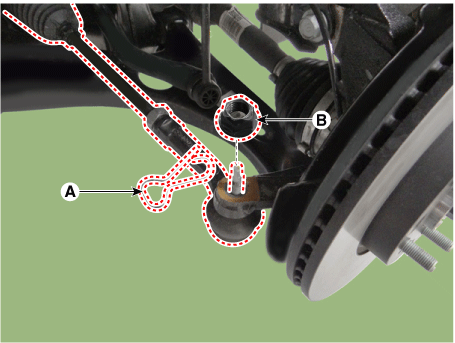
Disconnect the tie rod end ball joint from the knuckle using SST (09568-1C100).
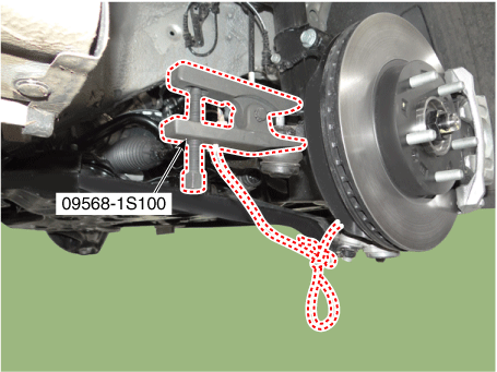
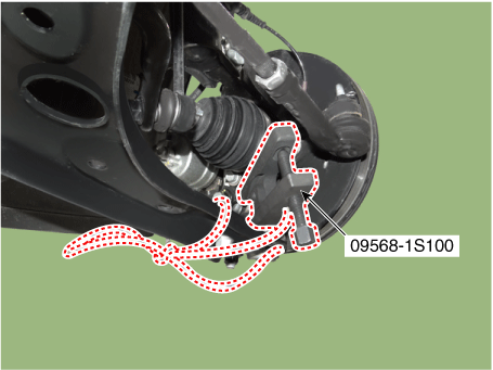
Disconnect the lower arm from the knuckle using SST (09568-1S100).
Remove the lower arm nut (A).
Tightening torque: 58.8–71 N·m
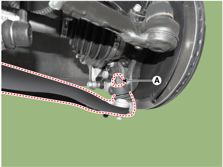
Disconnect the lower arm from the knuckle using SST (09568-1S100).
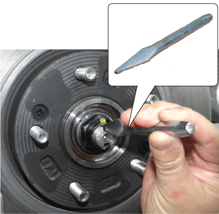
Unstake the drive shaft hub nut lock by tapping a chisel with a hammer.
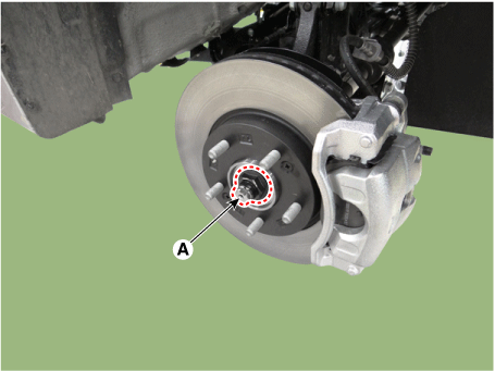
Remove the staked nut (A) from the front axle.
Tightening torque: 274.6–294 N·m
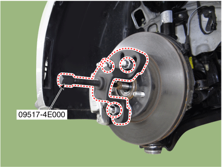
Using SST (09517-4E000), disconnect the propeller shaft from the axle hub.
Remove the driveshaft.
Insert a pry bar (A) between the transaxle case and the joint housing, and separate the drive shaft (B) from the transaxle case.
[LH]
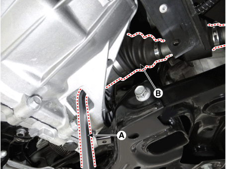
[RH - Gamma 1.6 MPI, Nu 2.0 MPI, New U 1.6 CRDi]
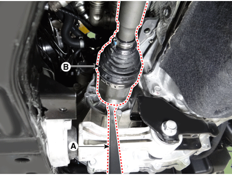
[RH - Gamma 1.6 T-GDI]
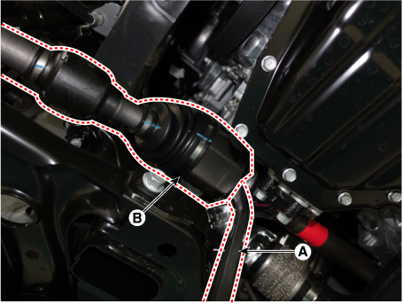
Remove the drive shaft (A).
[LH]
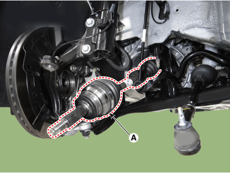
[RH - Gamma 1.6 MPI, Nu 2.0 MPI, New U 1.6 CRDi]
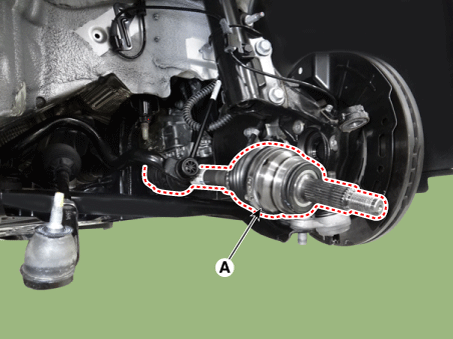
[RH - Gamma 1.6 T-GDI]
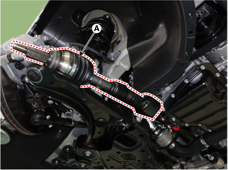
Install in the reverse order of removal.
Inspect the front wheel alignment.
(Refer to Suspension System - Front Wheel Alignment)
Bearing Bracket and Shaft Assembly
Remove the front drive shaft.
Remove the bearing bracket and shaft assembly (A).
Torque: 39.2 – 64 N·m
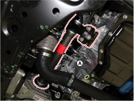
Install in the reverse order of removal.
Inspect the front wheel alignment.
(Refer to Suspension System - Front Wheel Alignment)
Test yourself
A quick Kia Forte BD quiz: every answer comes with an explanation and a link to the manual page.