Body Electrical System
Multifunction switch
In this manual: Body Electrical System
4steps
~24min
2/5difficulty
Done 0 of 4
Specifications
Specifications
| Items | Specifications | |
| Rated Voltage | Front Fog Light Switch | 5 V |
| Rear Fog Lamp Switch | ||
| Headlight Switch | ||
| Dimmer and Passing | ||
| Turn Signal Indicator | ||
| Wiper Arm | ||
| Front Washer | 12 V | |
Components and Component Location
Components
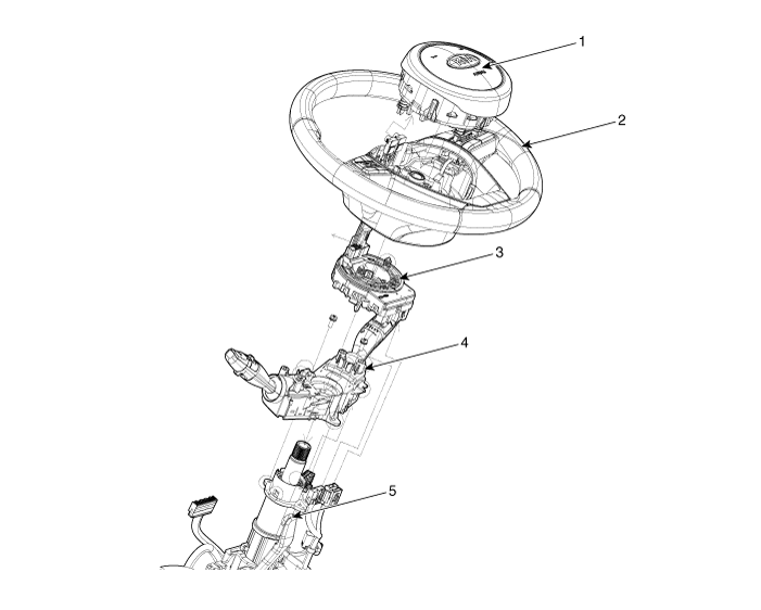
| 1. Driver Airbag Module (DAB) 2. Steering Wheel 3. Clock Spring |
4. Multifunction Switch 5. Steering Column |
Description and Operation
Description
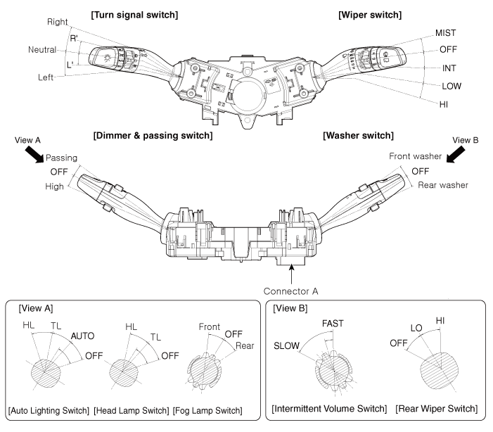
Circuit Diagrams
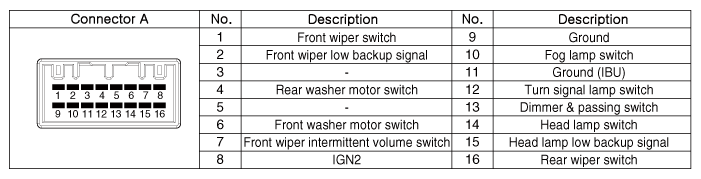
Connector and Terminal Function
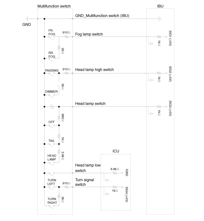
Schematic Diagram
Lighting System Circuit Diagram
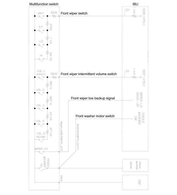
Wiper/Washer Circuit Diagram
Repair Procedures
Removal
Disconnect the negative (-) battery terminal.
Remove the clockspring.
(Refer to "Restraint System - Driver Airbag Module (DAB) and Clock Spring")
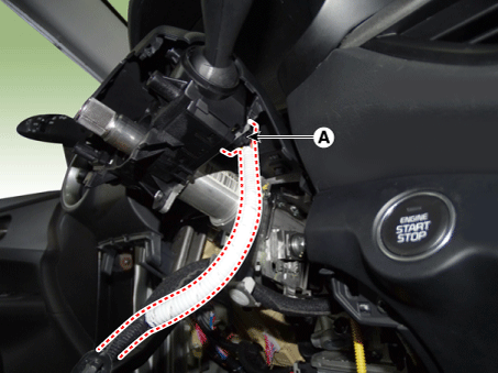
Disconnect the multifunction switch connector (A).
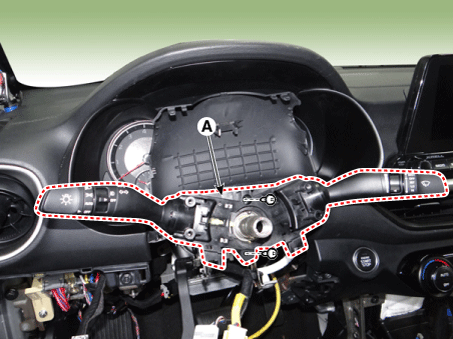
Remove the multifunction switch assembly (A) after loosening the screws.
Installation
Install in the reverse order of removal.
Inspection
Multifunction Switch Inspection
Check the continuity between terminals at each switch position in accordance with the table.
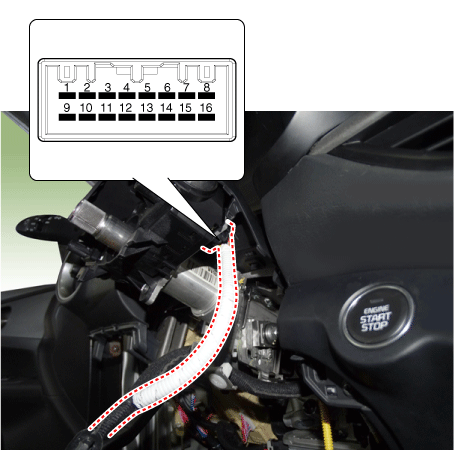
Switch Switch Position Switch Terminal Resistance (Ω, ±3.5%) Wiper Switch FOG 1-9 330 OFF ∞ INT (AUTO) 800 LOW 1800 HIGH 5700 Intermittent Wiper Volume Level 1 7-9 330 Level 2 690 Level 3 1310 Level 4 2610 Level 5 7310 Fog Light Switch OFF 9-10 ∞ Front 910 Rear 2910 Turn Signal Switch OFF 9-12 ∞ Left 910 Right 2910 Dimmer and Headlight Switch OFF 9-13 ∞ Passing 910 Dimmer 2910 Switch OFF 9-14 680 AUTO ∞ Rear Lamp 1680 Low Beam 5580
Test yourself
A quick Kia Forte BD quiz: every answer comes with an explanation and a link to the manual page.
Was this page helpful?