Keyless Entry and Theft Alarm System
Specifications
Specification
| Item | Specification |
| Power Supply | 3 V |
| Operating Temperature | 14–140°F (-10–60°C) |
| RF Modulation | FSK |
| LF Modulation | REQUEST |
| RF Frequency | 433.92 MHz |
| Button Number | 3 |
| Function | Lock |
| Door Unlock | |
| Unlocking the Trunk |
Components and Component Location
Components
[4DR]
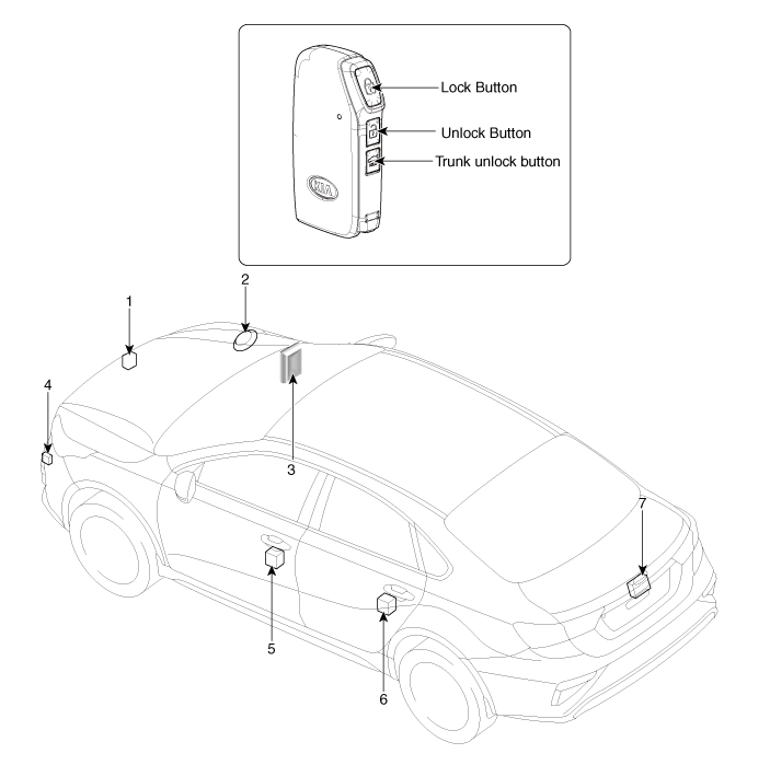
| 1. Hood switch 2. Theft alarm horn 3. Integrated Body Control Unit (IBU) 4. Door lock/unlock buzzer |
5. Front door actuator and switch 6. Rear door actuator and switch 7. Trunk actuator and switch |
[5DR]
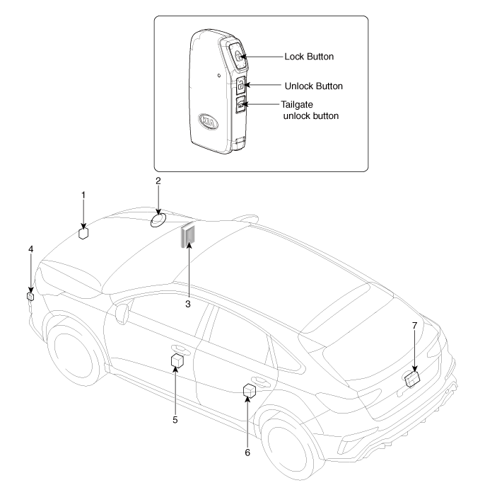
| 1. Hood switch 2. Theft alarm horn 3. Integrated Body Control Unit (IBU) 4. Door lock/unlock buzzer |
5. Front door actuator and switch 6. Rear door actuator and switch 7. Trunk actuator and switch |
Description and Operation
Description
Security Alarm Status [B/A Status]
| B/A Status | Description |
| DISARM |
|
| PREPARATION |
|
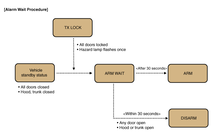
※ Note: For a vehicle equipped with the Smart Key System, the same process applies to the passive door lock function.
| B/A Status | Description |
| AUTO LOCK TIMER 1 |
|
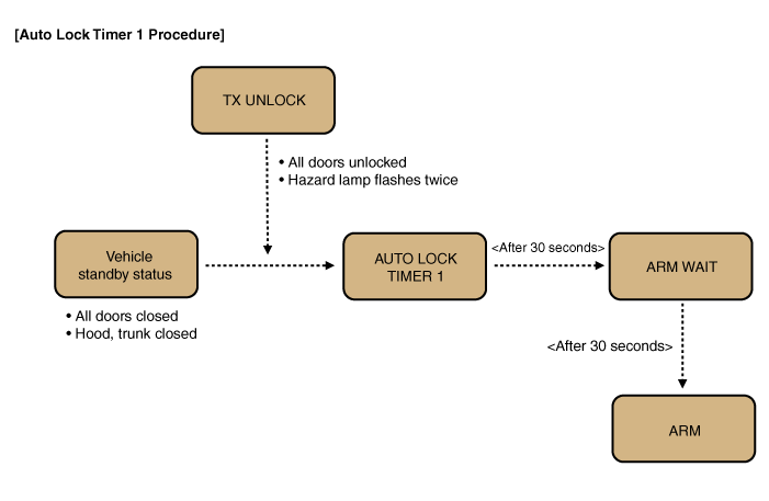
※ Note: For a vehicle equipped with the Smart Key System, the same process applies to the passive door lock function.
| B/A Status | Description |
| AUTO LOCK TIMER 2 |
|
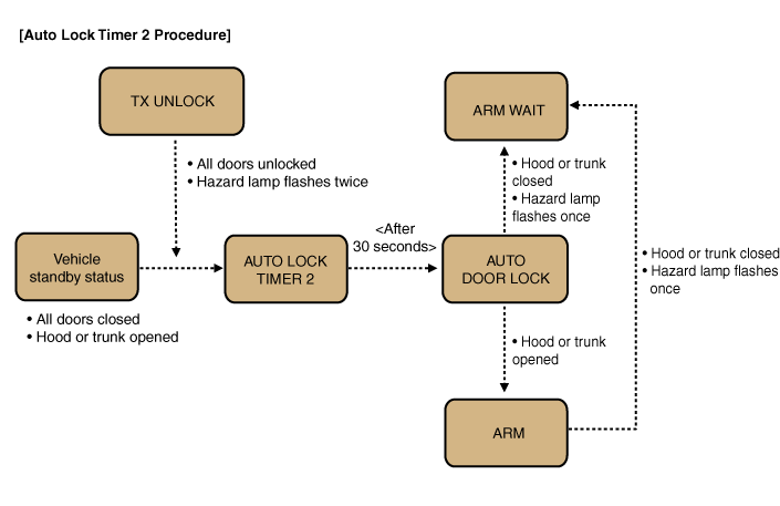
※ Note: For a vehicle equipped with the Smart Key System, the same process applies to the passive door lock function.
| B/A Status | Description |
| PREARM | 1-1. This is the state immediately before entering the "ARM" mode after AUTO LOCK. Timer 2 is completed and all doors are closed. 1-2. If the driver closes the hood or trunk, the alarm flashes once and then the vehicle automatically enters the "ARM" mode via the "ARM WAIT" mode. 2-1. If the LOCK button is pressed when at least one of the doors, the hood, or the trunk is open, the "PRE ARM" mode is activated. 2-2. Since the all-door lock signal is output but the conditions for "ARM WAIT" are not satisfied, the vehicle remains in the standby state and enters the ARM mode via the ARM WAIT state as soon as the open door is closed. 2-3. If an intrusion is detected in the PRE ARM mode, the alarm is activated. DISARM mode. 2-4. The security indicator continues to flash in the PRE ARM mode. |
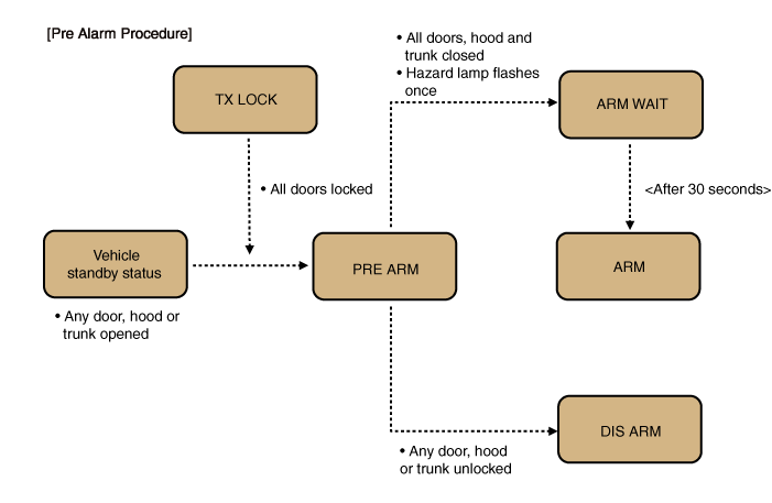
| B/A Status | Description |
| RE ARM |
|
| B/A Status | Description |
| AUTO LOCK TIMER 3 |
|
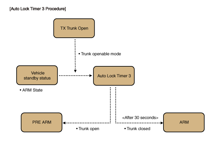
| B/A Status | Description |
| ARM HOLD (Alarm Hold: Trunk) ※ Variant without PTL |
|
Note 1: ARM HOLD is a mode that delays activation of the ARM mode for the linkage line only. In ARM HOLD mode, the ARM mode applies to the doors and hood.
Note 2: When the ignition key is used to open the trunk, the ARM HOLD function operates in the same way, provided that the "Key Alarm" function is enabled. If this is disabled, the key-based ARM HOLD is disabled and opening the trunk with the key is determined to be theft and an alarm is triggered.
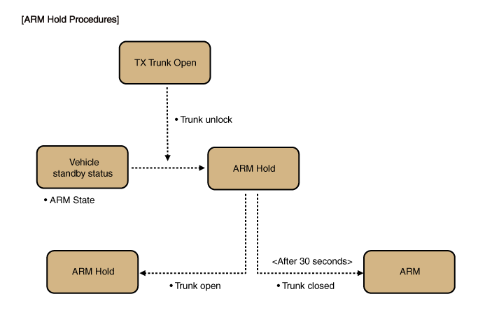
| B/A Status | Description |
| RE ARM (ARM mode re-enabled) |
|
| RESET |
|
| B/A Status | Description |
| KEY ON 30-second deactivation (non-smart key version) |
|
| When ARM mode is enabled, opening the trunk and central door unlocking are not allowed. |
|
Repair Procedures
Inspection
Front Door Lock Module
Remove the front door trim panel.
(Refer to Body - "Front Door Trim Panel")
Remove the front door module.
(Refer to Body - "Front Door Module")
Disconnect the connector from the door lock actuator.
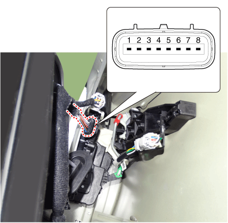
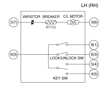
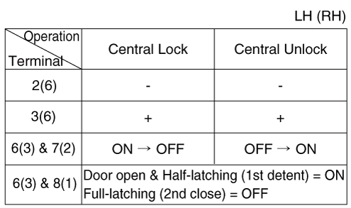
No. Description Left Right 1 - Ajar Switch 2 COM Motor Lock/Unlock Switch 3 Motor www.switch.com 4 Key interlock switch Key unlock switch 5 Key unlock switch Key interlock switch 6 www.switch.com Motor 7 Lock/Unlock Switch COM Motor 8 Ajar Switch - Check the actuator operation by connecting power and ground as shown below. To avoid damaging the actuator, apply battery voltage only momentarily.
Rear Door Lock Module
Remove the rear door trim.
(Refer to Body - "Rear Door Trim Panel")
Remove the rear door module.
(Refer to Body - "Rear Door Module")
Disconnect the connector from the door lock actuator.
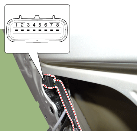
No. Description Left Right 1 - Ajar Switch 2 COM Motor Lock/Unlock Switch 3 Motor www.switch.com 4 - - 5 - - 6 www.switch.com Motor 7 Lock/Unlock Switch COM Motor 8 Ajar Switch - Check the actuator operation by connecting power and ground as shown below. To avoid damaging the actuator, apply battery voltage only momentarily.
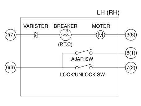
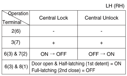
Trunk Lock Module [4DR]
Remove the trunk lid trim.
(Refer to Body - "Trunk Lid Trim")
Disconnect the connector from the trunk lid lock.
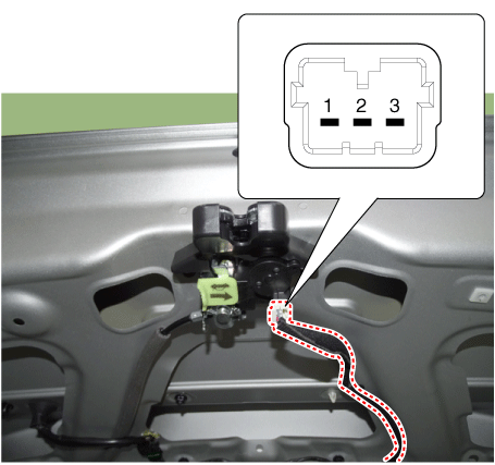
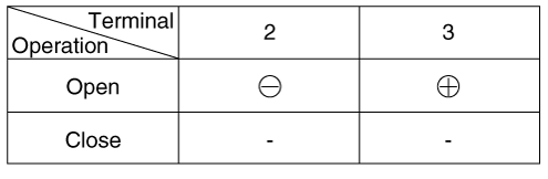
Check the actuator operation by connecting power and ground as shown below. To avoid damaging the actuator, apply battery voltage only momentarily.
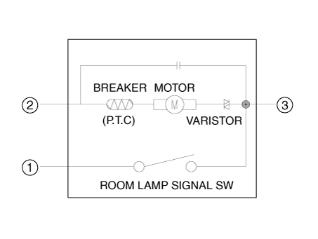
Rear Door Lock Module [5DR]
Remove the trunk lid trim panel.
(Refer to Rear Door - "Rear Door Trim")
Disconnect the connector from the trunk lid lock.
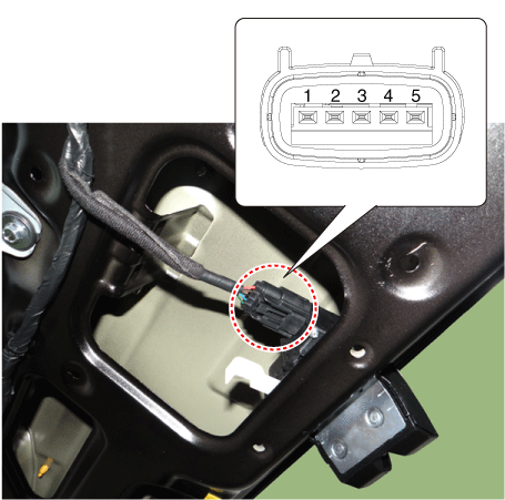
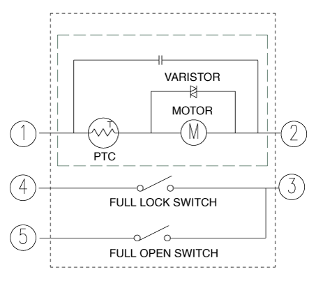
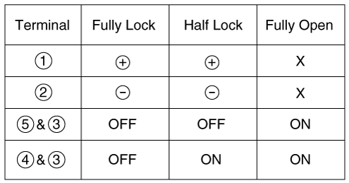
Check the actuator operation by connecting power and ground as shown below. To avoid damaging the actuator, apply battery voltage only momentarily.
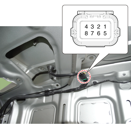
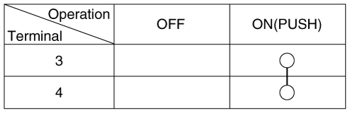
Trunk Lid Handle [4DR]
Check the circuit between the terminals for continuity.
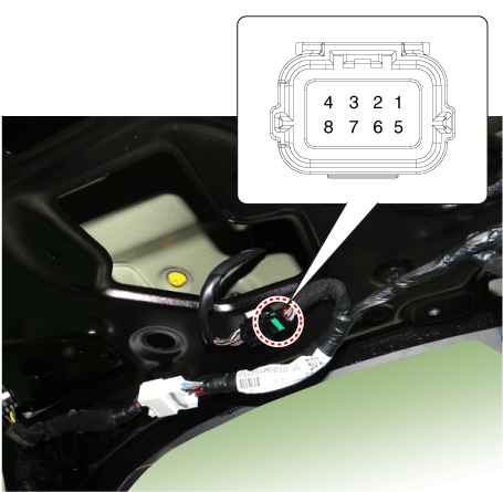
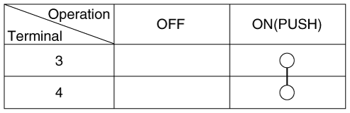
Trunk Lid Handle [5DR]
Remove the trunk lid trim panel.
(Refer to Rear Door - "Rear Door Trim")
Check the circuit between the terminals for continuity.
Hood Switch
Check the circuit between the terminals for continuity.
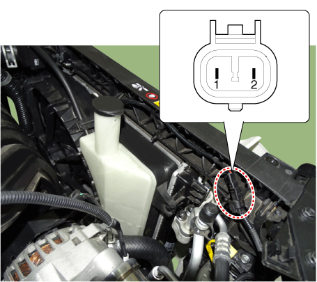
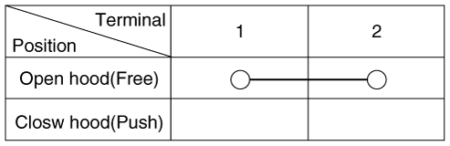
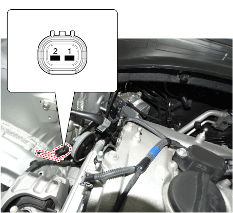
Burglar Horn
Check the horn by connecting battery power to terminal 2 and grounding terminal 1.
Removal
Front Door Lock Module
Remove the front door latch.
(Refer to Body - "Front Door Latch")
Rear Door Lock Module
Remove the liftgate latch.
(Refer to Body - "Rear Door Latch")
Trunk Lock Module [4DR]
Remove the trunk lid lock.
(Refer to Body - "Trunk Lid Latch")
Rear Door Lock Module [5DR]
Remove the luggage compartment lid latch.
(Refer to Body - "Rear Door Latch")
Trunk Lid Handle [4DR]
Disconnect the negative (-) battery terminal.
Remove the trunk lid trim.
(Refer to Body - "Trunk Lid Trim")
Remove the inside rear combination light.
(Refer to Lighting System - "Rear Combination Light")
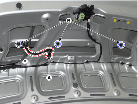
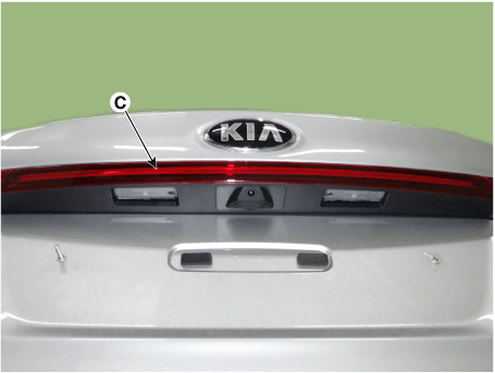
Disconnect the connector (A) and remove the trunk lid rear panel (C) by loosening the nuts (B).
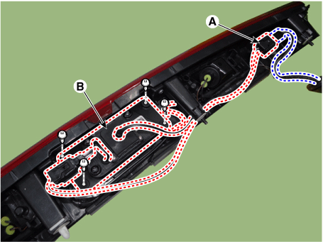
Disconnect the connector (A), then remove the rear view camera and luggage compartment door handle assembly (B) after loosening the screws.
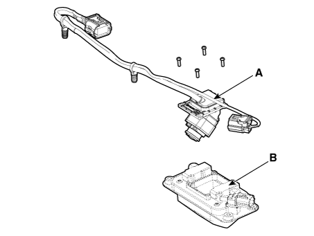
Remove the rear view camera (A) by removing the luggage compartment door handle mounting screw. Remove the door handle (B).
Trunk Lid Handle [5DR]
Disconnect the negative battery cable.
Remove the rear door trim panel.
(Refer to Body - "Rear Door Trim Panel")
Loosen the rear door garnish bracket mounting screws.
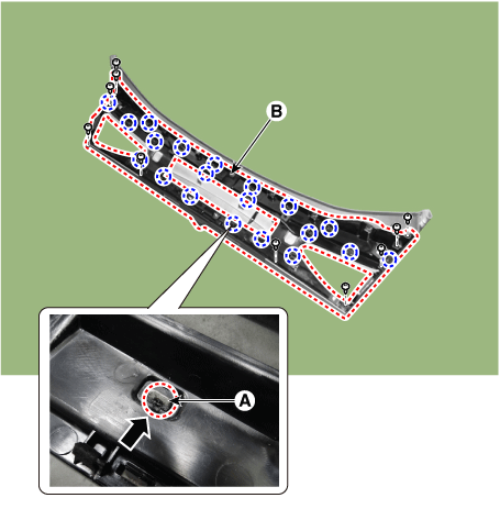
Remove the rear door garnish bracket (B) by pressing the retaining hooks (A) in the direction of the arrow.
Disconnect the rear view camera connector (A).
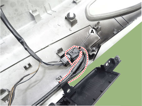
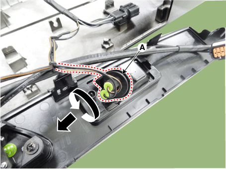
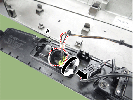
Remove the license plate lamp socket (A) by turning it counterclockwise.
[LH]
[RH]
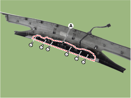
Remove the luggage compartment door rear garnish panel (A) after loosening the mounting screws.
Disconnect the luggage compartment door handle connector (A).
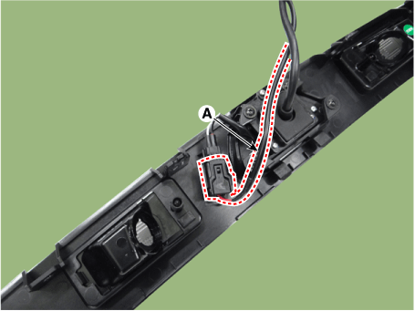
Remove the rear view camera and luggage compartment door handle assembly (A) after loosening the mounting screws.
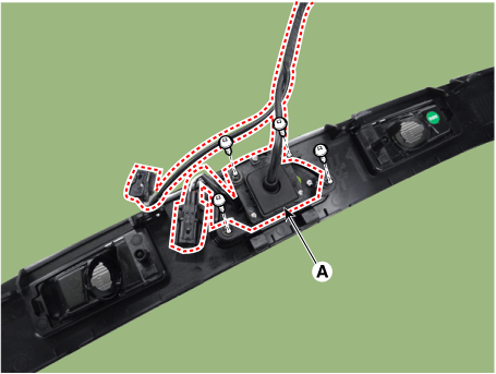
Loosen the rear view camera mounting screws (A).
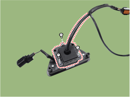
Remove the rear view camera (A) from the luggage compartment door handle (B).
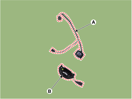
Hood Switch
Remove the hood latch.
(Refer to Body - "Hood Latch")
Burglar Horn
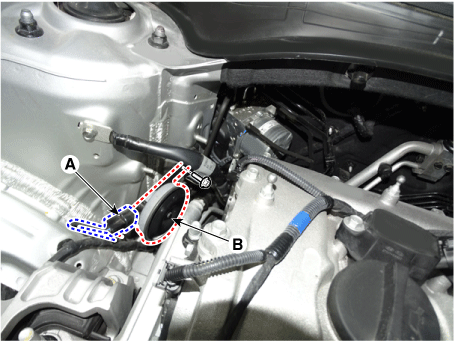
Disconnect the connector (A) and remove the horn (B) by loosening the bolt.
Install in the reverse order of removal.
Installation
Install in the reverse order of removal.
Test yourself
A quick Kia Forte BD quiz: every answer comes with an explanation and a link to the manual page.