Front Camera System
Components and Component Location
Components
[4DR]
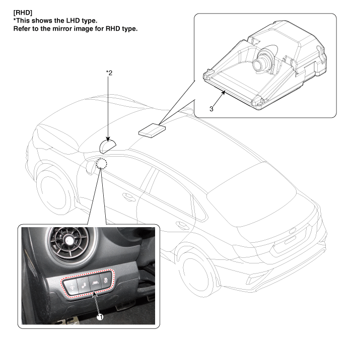
| 1. LKA ON/OFF Switch 2. Instrument Cluster |
3. Front View Camera |
[5DR]
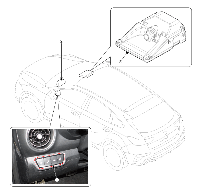
| 1. LKA ON/OFF Switch 2. Instrument Cluster |
3. Front View Camera |
Description and Operation
Description
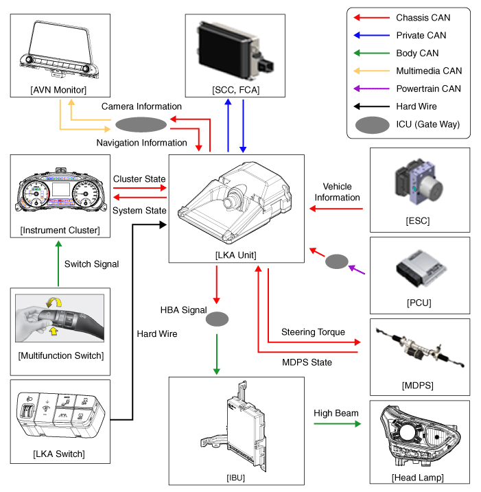
System Block Diagram
System Features
The LKA camera module processes the following functions using the input video signal.
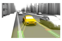
LKA (Lane Keeping Assist): The system is designed to help recognize the lane ahead and provide a warning when the vehicle begins to drift out of its lane, using camera images and vehicle information signals.
High Beam Assist (HBA): Detects the headlights and taillights of vehicles ahead and turns the high beams on/off.
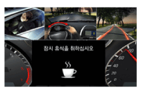
Driver Attention Warning (DAW): Provides a quick alert and warning message through analysis of the driving pattern.
Highway Driving Assist (HDA): An integrated control function that maintains the distance to the vehicle ahead and keeps the vehicle in the lane on the highway through interaction with the SCC radar.
| Lane Keep Assist (LKA) | High Beam Assist (HBA) |
 |
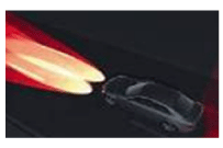 |
| Lane Keeping System | When light from a vehicle ahead is detected |
| Driver Attention Warning (DAW) | Highway Driving Assist (HDA) |
 |
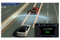 |
| Alert when the driver is not paying attention to driving. | Steering and speed control on the highway. |
System Activation Conditions
Typical Operating Conditions of the LKA Controller
Note that the operating conditions are adapted to customer requirements.
Vehicle speed within 60–175 km/h
Lane markings are clearly visible.
The driver does not overload the system by applying high torque to the steering wheel.
Turn signals (including hazard lights) are off.
Lane width from 2.8 m to 4.3 m.
The driver's hands are on the steering wheel.
Absolute steering wheel angle is less than the specified value (e.g., 90 degrees).
The maximum allowable time for applying maximum torque has not been exceeded (90 seconds).
Reverse or city mode of EPS is not engaged.
There is no system malfunction.
The HBA activation conditions are as follows:
HBA is activated when the light switch is in the "AUTO" position and the high beam switch is turned on (pressed).
HBA is activated when the function is enabled and vehicle speed is 45 km/h or higher, and is automatically deactivated when vehicle speed is 35 km/h or lower.
HBA does not activate during daytime, even if the activation conditions are met.
At night, HBA detects the light of vehicles ahead and automatically turns the high beams on or off.
The DAW activation conditions are as follows:
This function must be enabled in the User Setting Mode (USM) of the cluster.
The function must be enabled and vehicle speed must be 60 – 175 km/h.
Repair Procedures
Adjustment
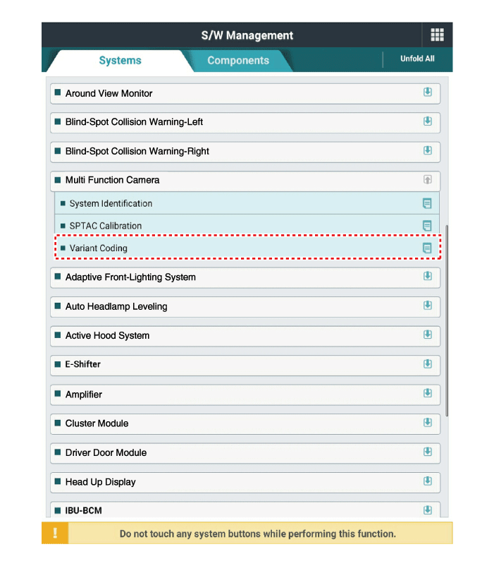
Option Coding Procedures
When the front camera module is replaced with a new one, option coding is required because the vehicle must learn the option specifications of the original vehicle.
Complete the option coding procedure by following the instructions on the connected KDS screen.
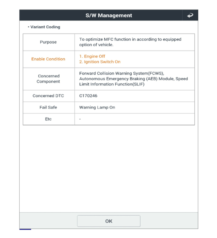
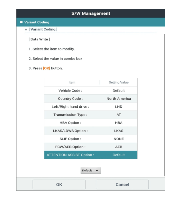

Service Point Target Automatic Calibration (SPTAC)
The SPTAC front view camera calibration provides a procedure for calibrating the camera by aligning the calibration target (SST: 09890-3V100) with the vehicle on a level surface.
If calibration is not completed within the specified tolerance, the front view camera displays a "System Out of Calibration" DTC.
Correct Alignment Method of the Calibration Target
To perform the front view camera calibration successfully, install the calibration target as follows:
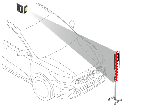
Install the target (SST: 09890-3V100) perpendicular to the ground and facing the camera, referring to the tolerance angles below.
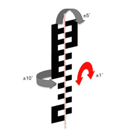
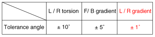
Project the laser from the center of the roof to the center of the target, passing through the center of the emblem.
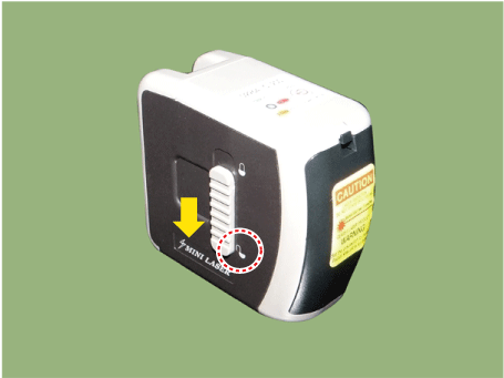
* The laser level must be set to "ON", and the hold (lock) function must not be used.
Service Point Target Automatic Calibration (SPTAC) Procedure
It is recommended to check the vehicle wheel alignment and tire pressure to ensure correct camera alignment to the "world" before proceeding with calibration.
The vehicle used for the calibration procedure must be at its rated production load capacity.
The windshield must be clean and free of silkscreen so that there is no obstruction to the camera.
The service technician connects the diagnostic connector and starts the vehicle. The MFC must not be activated by pressing the switch.
The service calibration procedure may not work correctly if a system-level fault is active.
When working with a replacement ECU: the service technician initiates the SPTAC reset configuration.
The service technician aligns either the vehicle to the target or the target to the vehicle.
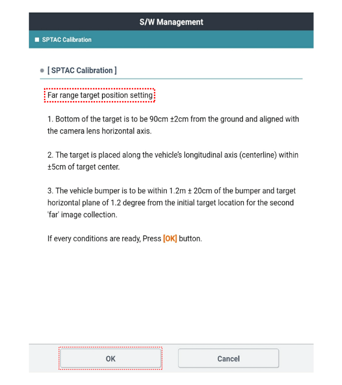
a. Locate the bottom of the target at a height of 90 cm from the ground (max. tolerance: 1 cm).
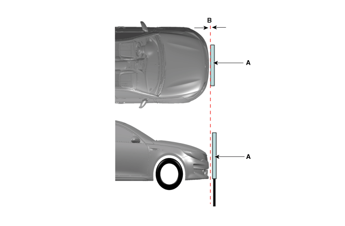
b. Locate the near target (A) so that it is 0 cm (B) from the front of the bumper (max. tolerance: 5 cm).
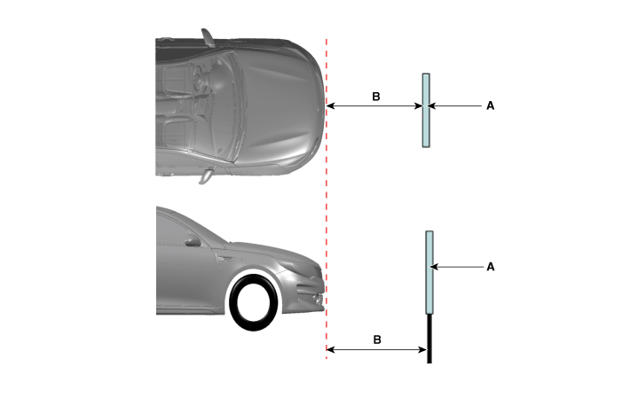
b. Locate the far target (C) at 100 cm (D) in front of the bumper (max. tolerance: 5 cm).
The service technician must perform short-distance calibration after checking the target location and the "OK" message on the KDS.
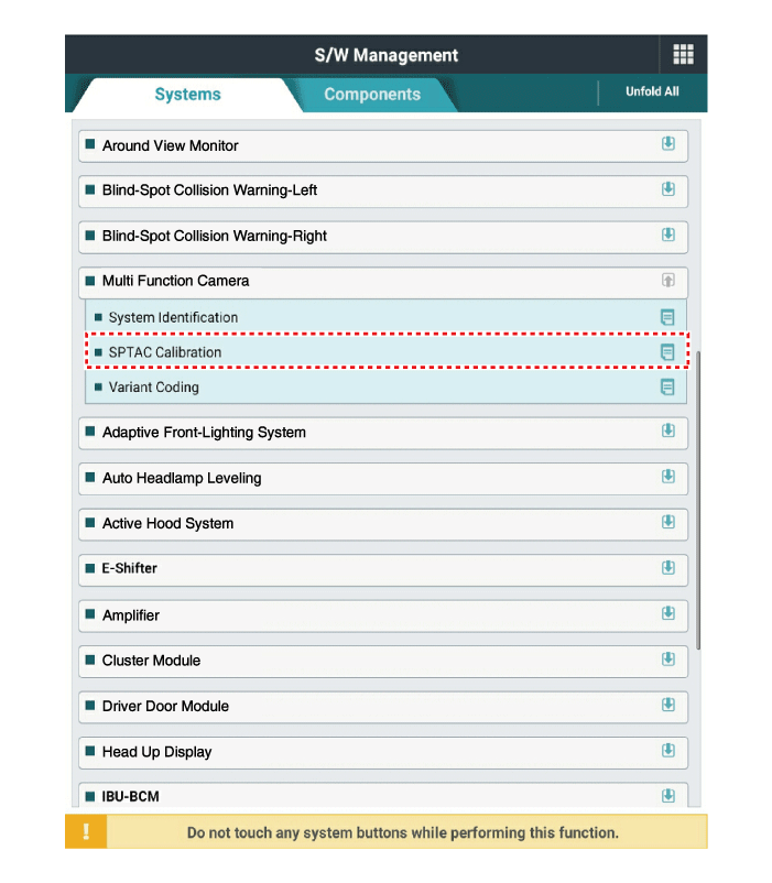
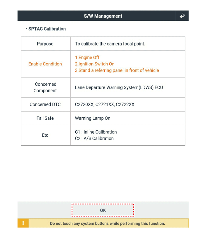
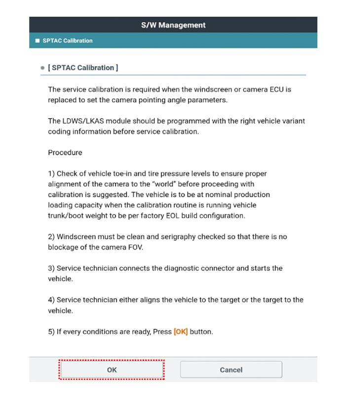
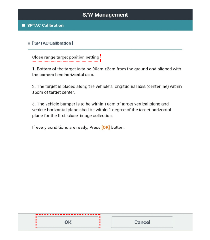

The service technician must perform long-distance calibration after checking the target location and the "OK" message on the KDS (perform calibration twice: short and long distance).

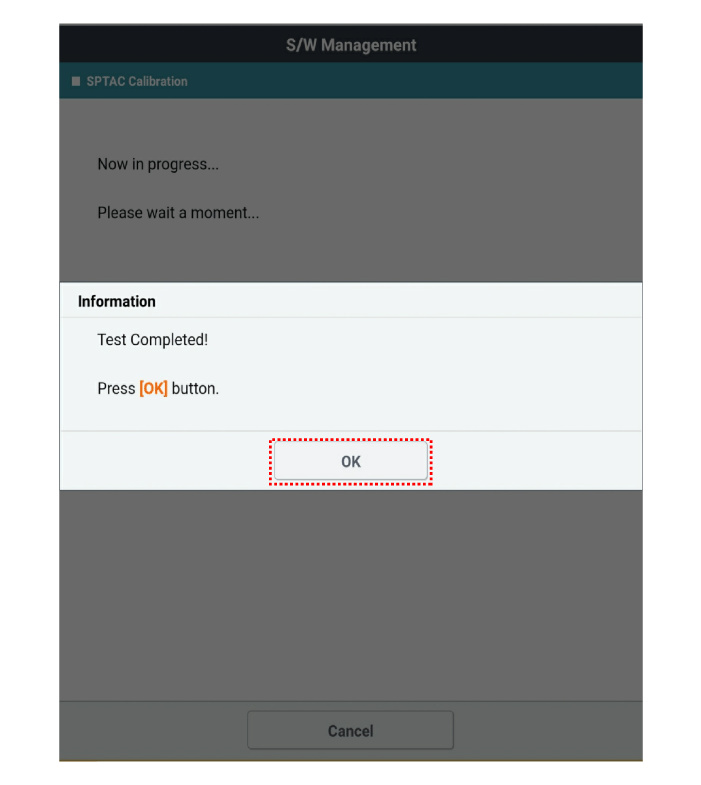
Clear the diagnostic trouble codes.
Restart after turning off the engine.
Test Drive
Test yourself
A quick Kia Forte BD quiz: every answer comes with an explanation and a link to the manual page.