Automatic Transmission
Solenoid Valve SS-B (ON/OFF) Repair Procedures
In this manual: Automatic Transmission
18steps
~108min
4/5difficulty
Done 0 of 18
Inspection
- Turn the ignition off.
- Remove the air duct (A).
Tightening torque: 7.8 ~ 9.8 N·m
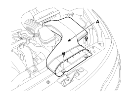
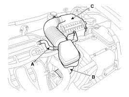
- Remove the air cleaner assembly.
- Disconnect the breather hose (A).
- Disconnect the air intake hose (B) and remove the air cleaner assembly (C).

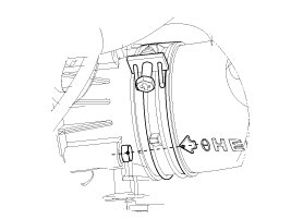
- When installing the air intake hose, align the clamp plate with the hose stopper.
- When installing the air intake hose, align the center of the mark on the hose with the rib of the throttle body.
- Disconnect the solenoid valve connector.
- Measure the resistance between the signal terminal and the ground terminal.
- Make sure the resistance is within specification.
Removal
|

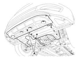
- Remove the lower cover (A).
Tightening torque: 7.8 ~ 11.8 N·m
- Drain the coolant from the hybrid engine cooling system. (Refer to Hybrid Powertrain System - "Engine Coolant")
- Drain the coolant from the engine and transaxle cooling system. (Refer to Engine Mechanical System - "Engine Coolant")
- Remove the drain plug (A) and reinstall it after completely draining the ATF.
Tightening torque: 33.3 ~ 43 N·m
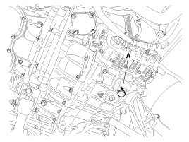
- Remove the fixing clip of the valve body wire ring (A).
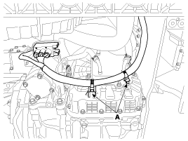
- Remove the air duct (A).
- Remove the air cleaner assembly.
- Disconnect the breather hose (A).
- Disconnect the air intake hose (B) and remove the air cleaner assembly (C).
- Remove the hybrid power control unit (HPCU) assembly. (Refer to Hybrid Control System - "HPCU (Hybrid Power Control Unit)")
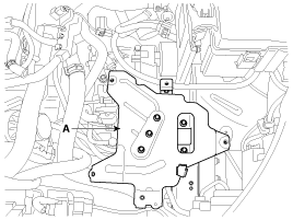
- Remove the HPCU tray (A).
Tightening torque: 19.6 ~ 29 N·m (2.0 ~ 3.0 kgf·m, 14.5 ~ 21.7 lbf·ft)
- Remove the automatic transmission oil cooler tube (A). Tightening torque: Banjo bolt: 41.2 ~ 47 N·m Bracket bolt: 9.8 ~ 11.8 N·m
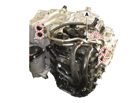
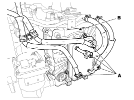
- Remove the valve body cover bolt after removing the ATF heater hose (A).
Tightening torque: 11.8 ~ 13.7 N·m (1.2 ~ 1.4 kgf·m, 8.7 ~ 10.1 lbf·ft)
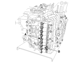
- Remove the solenoid valve (B) after removing the solenoid valve support (A).
Installation
- Install in the reverse order of removal.
During installation, apply ATF or white petrolatum to the O-ring (A) to prevent damage during installation.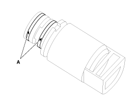
- Do not reuse the drain plug gasket, valve body cover gasket, and oil cooler tube washer.
- Be careful not to damage the hose when tightening the clamp.
- Install the clamp in the specified direction so that it does not interfere with surrounding components.
- After installation, perform the procedures described below.
- Fill the automatic transmission with fluid. (Refer to Hydraulic System — "Fluid").
- Fill the engine and transaxle cooling system with coolant. (Refer to Engine Mechanical System - "Coolant").
- Fill the hybrid engine cooling system with coolant, then perform air bleeding using GDS. (Refer to Hybrid Powertrain System - "Engine Coolant")
- Perform the procedure to store the TCM adaptive values. (Refer to "Automatic Transmission Control System - Repair Procedures")
- With the engine running, check for coolant leaks or fluid leaks from the hose connections.
Test yourself
A quick Kia Optima Hybrid Owner's Manual quiz: every answer comes with an explanation and a link to the manual page.
Was this page helpful?