Be sure to read and observe the "General Safety Information and Caution" before performing any work on the high voltage system. Failure to follow the safety instructions may result in serious electrical injury.
Perform a visual inspection to determine whether the vehicle requires general repair or post-accident repair.
For general repair, perform the repair according to the repair procedure for the applicable DTC.
For post-accident repair, determine the type of accident before performing repairs.
1) Electrical Accidents
Overcharge/Overdischarge: Indicates battery overvoltage. Code (P1B71) / low voltage code (P1B70) (refer to DTC troubleshooting guide).
Short: Indicates high voltage short circuit codes (P1B77, P1B25) (refer to DTC troubleshooting guide).
2) Fire
Classification
Inspection Procedure
Inspection Results
Action
Fire outside the high voltage battery mounting area
e.g. engine compartment fire
Perform a visual inspection (deformation, corrosion, wire insulation, odor, connector).
After disconnecting high voltage, check the main fuse circuit for an open circuit.
Check the main high voltage relay for signs of welding.
Measure the insulation resistance of the high voltage battery/housing.
Check other components for malfunction.
Check the DTC in the BMS ECU.
High voltage battery insulation is damaged
Remove the high voltage battery and repair the insulation/coating.
High voltage battery is not damaged
Malfunction Code
If a DTC is present, follow the DTC troubleshooting guide and repair procedure.
No DTC and the battery appears normal
Do not replace the high voltage battery (if the battery is damaged and must be disposed of, perform the high voltage battery disposal procedure).
Fire in the high voltage battery rack
e.g. luggage compartment fire
Perform a visual inspection (deformation, corrosion, wire insulation, odor, connector).
Check the high voltage battery for visible damage.
After disconnecting high voltage, if no visible damage is found in the high voltage battery, check the main high voltage relay for signs of welding.
Measure the insulation resistance of the high voltage battery/housing.
Check other components for malfunction.
Check the DTC in the BMS ECU.
High voltage battery appears damaged (heat, soot, etc.)
Remove the service disconnect plug and perform the salt water battery disposal procedure.
High voltage battery insulation is damaged
Remove the high voltage battery and repair the coating/insulation.
High voltage battery is not damaged
Malfunction Code
If a DTC occurs, perform the repair procedure described in the DTC troubleshooting guide.
No DTC and the battery appears normal
Do not replace the high voltage battery (if the battery is damaged and must be disposed of, perform the high voltage battery disposal procedure).
3) Collision
Classification
Inspection Procedure
Inspection Results
Action
Collision damage to areas other than the high voltage battery mounting
e.g. frontal/side collision
Perform a visual inspection (deformation, corrosion, wire insulation, odor, connector).
After disconnecting high voltage, check the main fuse circuit for an open circuit.
Check the main high voltage relay for signs of melting.
Measure the insulation resistance of the high voltage battery/housing.
Check other components.
Check the DTC in the BMS ECU.
High voltage battery insulation is damaged
Remove the high voltage battery and repair the coating/insulation.
High voltage battery is not damaged
Malfunction Code
If a DTC occurs, perform the repair procedure described in the DTC troubleshooting guide.
No DTC and the battery appears normal
Do not replace the high voltage battery (if the battery is damaged and must be disposed of, perform the high voltage battery disposal procedure).
Collisions with the high voltage battery support
Example) Rear collision
Perform a visual inspection (deformation, corrosion, wire insulation, odor, connector).
After disconnecting high voltage, check the main fuse circuit for an open circuit.
Check the main high voltage relay for signs of melting.
Measure the insulation resistance of the high voltage battery/housing.
Check other components.
Check the DTC in the BMS ECU.
High voltage battery insulation is damaged
Observe the precautions described above. If the high voltage battery mounting is inaccessible due to damage to the luggage compartment or door, or bent or cut outer panels, inspect and repair without damaging the voltage system.
High voltage battery is not damaged
Malfunction Code
No DTC and the battery appears normal
4) Immersion
Classification
Inspection Procedure
Inspection Results
Action
High voltage battery is not submerged in water
Perform a visual inspection (deformation, corrosion, wire insulation, odor, connector).
After disconnecting high voltage, check the main fuse circuit for an open circuit.
Check the main high voltage relay for signs of melting.
Measure the insulation resistance of the high voltage battery/housing.
Check other components.
Check the DTC in the BMS ECU.
High voltage battery insulation is damaged
Remove the high voltage battery and repair the coating/insulation.
High voltage battery is not damaged
Malfunction Code
If a DTC occurs, perform the repair procedure described in the DTC troubleshooting guide.
No DTC and the battery appears normal
Do not replace the high voltage battery (if the battery is damaged and must be disposed of, perform the high voltage battery disposal procedure).
High voltage battery is submerged in water [Regardless of water condition]
After disconnecting high voltage, check the main fuse circuit for an open circuit.
Check the main high voltage relay for signs of melting.
Measure the insulation resistance of the high voltage battery/housing.
Check the DTC in the BMS ECU.
Perform these actions regardless of inspection results
Remove the high voltage battery and repair the coating/insulation.
Main Fuse Inspection
Be sure to read and observe the "General Safety Information and Caution" before performing any work on the high voltage system. Failure to follow the safety instructions may result in serious electrical injury.
Before performing any work, be sure to disconnect high voltage related to the high voltage system (refer to "High Voltage Disconnection Procedure"). Failure to follow safety instructions may result in serious electric shock.
When removing the battery assembly for inspection, the battery system can be connected to the vehicle using SST 0K918-E4100, 0K375-E4100, 0K375-E4200. Before installing the battery assembly, check the battery system operation using the SST.
Method 1
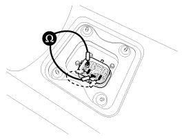
Remove the safety plug. (Refer to High Voltage Battery Management System - "Safety Plug").
Measure the resistance of the safety plug cable connected to the main fuse.
Specification: Less than 1 Ω (20°C)
Method 2
Turn the ignition OFF and disconnect the negative (-) terminal of the auxiliary battery.
Disconnect high voltage. (Refer to High Voltage Battery Management System - "High Voltage Disconnection Procedure")
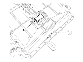
Remove the upper cover of the high voltage battery. (Refer to High Voltage Battery System - "Housing")
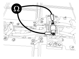
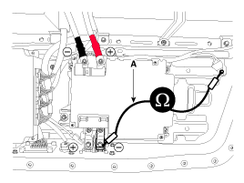
Remove the upper fuse block (A).
Perform an electrical inspection of the main fuse.
Specification: Less than 1 Ω (20°C)
Main High Voltage Relay Weld Inspection
When removing the battery assembly for inspection, the battery system can be connected to the vehicle using SST 0K918-E4100, 0K375-E4100, 0K375-E4200. Before installing the battery assembly, check the battery system operation using the SST.
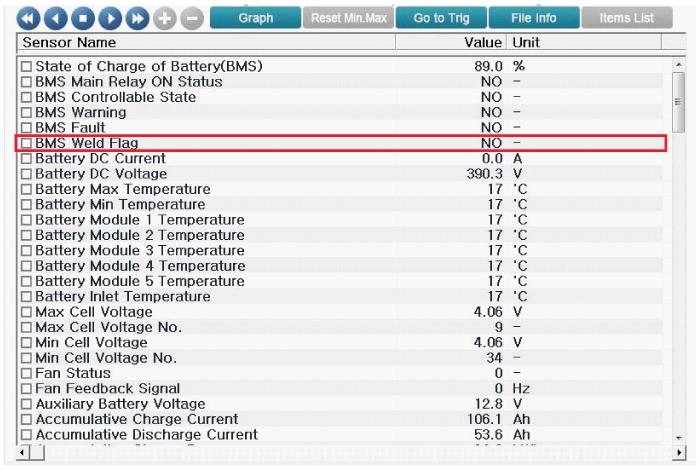
To safely remove the high voltage battery assembly, first inspect the main high voltage relay for signs of weld damage. You can use the Global Diagnostic System (GDS) service data to check for weld damage in the main high voltage relay.
Connect GDS to the DLC.
Turn the ignition on.
Check the BMS weld damage status in GDS service data.
Specification: NO
Be sure to read and observe the "General Safety Information and Caution" before performing any work on the high voltage system. Failure to follow the safety instructions may result in serious electrical injury.
Before performing any work, be sure to disconnect high voltage related to the high voltage system (refer to "High Voltage Disconnection Procedure"). Failure to follow safety instructions may result in serious electric shock.
Disconnect high voltage. (Refer to "High Voltage Disconnection Procedure")
Remove the high voltage battery assembly. (Refer to High Voltage Battery System - "Battery Assembly")
Remove the upper case. (Refer to High Voltage Battery System - "Housing")
Remove the protective cover (A) of the Power Relay Assembly (PRA).
Check the main high voltage relay for weld damage.
Specification: ?? Ω (20°C)
Insulation Resistance Inspection (with vehicle)
When removing the battery assembly for inspection, the battery system can be connected to the vehicle using SST 0K918-E4100, 0K375-E4100, 0K375-E4200. Before installing the battery assembly, check the battery system operation using the SST.
The insulation condition between the vehicle and the high voltage battery can be checked using GDS or by measuring resistance.
Connect GDS to the DLC.
Turn the ignition on.
Check the insulation resistance in the GDS service data.
Specified value: 300 kΩ to 1000 kΩ
Be sure to read and observe the "General Safety Information and Caution" before performing any work on the high voltage system. Failure to follow the safety instructions may result in serious electrical injury.
Before performing any work, be sure to disconnect high voltage related to the high voltage system (refer to "High Voltage Disconnection Procedure"). Failure to follow safety instructions may result in serious electric shock.
Disconnect high voltage. (Refer to High Voltage Battery Management System - "High Voltage Disconnection Procedure")
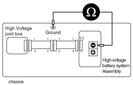
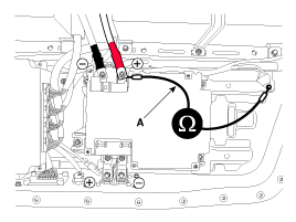
Connect the negative (-) lead of the megohmmeter (A) to the vehicle body ground.
For accurate measurement, connect the negative (-) lead to unpainted parts.
After connecting the positive (+) lead to the positive (+) battery terminal, measure the resistance as follows.
Apply 500 V with the megohmmeter, then wait approximately 1 minute to measure a stable resistance value.
Check the resistance.
Specified value: more than 2 MΩ (20°C)
After connecting the positive (+) lead to the negative (-) battery terminal, measure the resistance as follows.
Apply 500 V with the megohmmeter, then wait approximately 1 minute to measure a stable resistance value.
Check the resistance.
Specified value: more than 2 MΩ (20°C)
Insulation Resistance Check (With Battery)
Be sure to read and observe the "General Safety Information and Caution" before performing any work on the high voltage system. Failure to follow the safety instructions may result in serious electrical injury.
Before performing any work, be sure to disconnect high voltage related to the high voltage system (refer to "High Voltage Disconnection Procedure"). Failure to follow safety instructions may result in serious electric shock.
Remove the high voltage battery assembly. (Refer to High Voltage Battery System - "Battery Assembly")
Remove the high voltage battery upper case assembly. (Refer to High Voltage Battery System - Case)
Remove the protective cover (A) of the Power Relay Assembly (PRA).
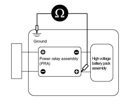
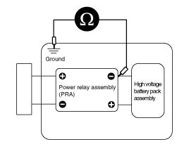
Connect the negative (-) lead of the megohmmeter to the lower case.
For accurate measurement, connect the negative (-) lead to unpainted parts.
Connect the positive (+) lead to the high voltage battery terminals (+, -) to measure the resistance.
Connect the positive (+) lead of the megohmmeter (A) to the PRA high voltage positive (+) terminal.
Apply 500 V with the megohmmeter, then wait approximately 1 minute to measure a stable resistance value.
Check the resistance value.
Specified value: more than 2 MΩ (20°C)
Connect the positive (+) lead of the megohmmeter (B) to the PRA high voltage negative (-) terminal.
Apply 500 V with the megohmmeter, then wait approximately 1 minute to measure a stable resistance value.
Check the resistance value.
Specified value: more than 2 MΩ (20°C)
Connect the positive (+) lead of the megohmmeter (A) to the PRA inverter power positive (+) terminal.
Apply 500 V with the megohmmeter, then wait approximately 1 minute to measure a stable resistance value.
Check the resistance value.
Specified value: more than 2 MΩ (20°C)
Connect the positive (+) lead of the megohmmeter (A) to the PRA inverter power negative (-) terminal.
Apply 500 V with the megohmmeter, then wait approximately 1 minute to measure a stable resistance value.
Check the resistance value.
Specified value: more than 2 MΩ (20°C)
Storage, Transportation and Disposal Guide for High Voltage Battery Systems
1. High Voltage Battery System Handling Procedure
2. Handling/Inspection of Malfunctioning High Voltage Battery System
Classification
?
Test yourself
A quick Kia Soul EV Owner's Manual quiz: every answer comes with an explanation and a link to the manual page.