Be sure to read and observe the "General Safety Information and Caution" before performing any work on the high voltage system. Failure to follow the safety instructions may result in serious electrical injury.
Before performing any work, be sure to disconnect high voltage related to the high voltage system (refer to "High Voltage Disconnection Procedure"). Failure to follow safety instructions may result in serious electric shock.
Turn the ignition OFF and disconnect the negative (-) terminal of the auxiliary battery.
Disconnect the high voltage. (Refer to "High Voltage Disconnection Procedure".)
Raise the vehicle.
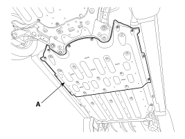
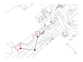
Loosen the nut and remove the front lower cover of the high voltage battery (A).
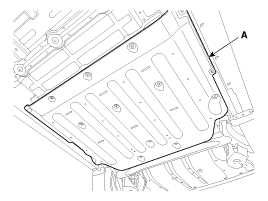
Loosen the nut and remove the rear lower cover of the high voltage battery (A).
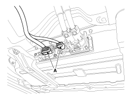
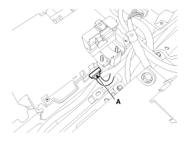
Disconnect the BMS connector (A).
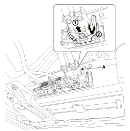
Disconnect the high voltage cable (A).
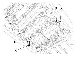
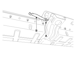
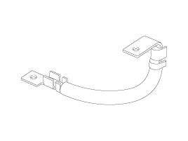
Disconnect the ground cable (B) by loosening the mounting bolt (A). Ground cable mounting bolt: 7.8 ~ 11.8 N·m
Support the high voltage battery assembly with a jack (A).
Securely support the battery pack with a jack to prevent accidents.
Make sure the high voltage cable and connectors are fully removed before removing the battery pack.
Place rubber on the jack to protect the bottom of the battery pack and the studs used to tighten the lower cover.
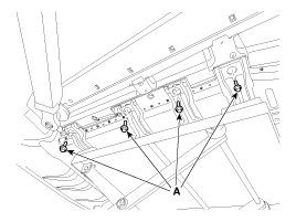
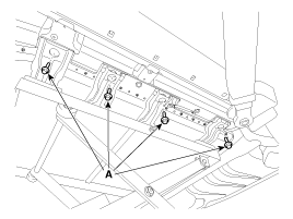
Loosen the mounting bolt of the high voltage battery assembly (A). High voltage battery assembly mounting bolt: 54.9 ~ 82 N·m [Front][Right][Left][Rear]
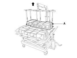
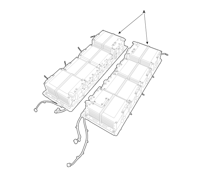
Remove the high voltage battery pack assembly (A) from the vehicle.
Disassembly
Be sure to read and observe the "General Safety Information and Caution" before performing any work on the high voltage system. Failure to follow the safety instructions may result in serious electrical injury.
Before performing any work, be sure to disconnect high voltage related to the high voltage system (refer to "High Voltage Disconnection Procedure"). Failure to follow safety instructions may result in serious electric shock.
Remove the high voltage battery pack. (Refer to High Voltage Battery System - Battery Pack Assembly - Repair Procedures - "Removal")
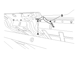
Remove the ground cable (B) by loosening the mounting bolt (A). [Right][Left]
Remove the mounting bolt of the service plug cable bracket (A). Service plug cable bracket mounting bolt: 7.8 ~ 11.8 N·m
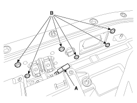
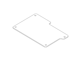
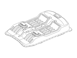
Loosen the mounting bolt and remove the upper case (A). High voltage battery upper case mounting bolt: 7.8 ~ 11.8 N·m
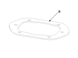
Remove the waterproof gasket (A).
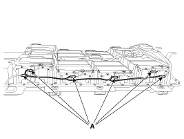
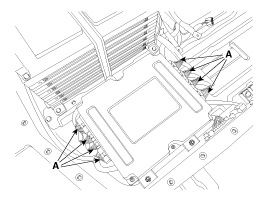
Disconnect the RAD wiring connector (A). [Right][Rear][Left]
Loosen the mounting nut and remove the battery module outlet duct (A). Battery module outlet duct mounting nut: 7.8 ~ 11.8 N·m
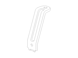
Loosen the mounting bolt and remove the bracket (A). Rear battery mounting bracket bolt: 7.8 ~ 11.8 N·m
Remove the high voltage power cable cover (A).
Loosen the nut (A), then disconnect the positive (+) high-voltage power cable (B). Positive (+) high-voltage power cable nut: 7.8 - 11.8 N·m
Loosen the nut (A), then disconnect the negative (-) high-voltage power cable (B). Negative (-) high-voltage power cable nut: 7.8 - 11.8 N·m
Remove the inverter bus bar cover (A).
Remove the inverter bus bar (A). Inverter bus bar bolt/nut: 7.8 - 11.8 N·m
Disconnect the high-voltage battery heating system control unit positive (+) power and ground connector (A). [With high voltage battery heating system]
Disconnect the power relay assembly connector (A).
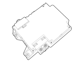
Loosen the mounting nut and remove the power relay assembly (A). Power relay assembly nut: 7.8 - 11.8 N·m
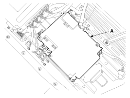
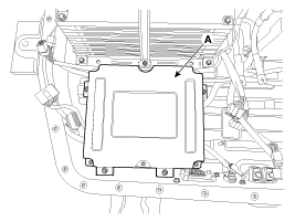
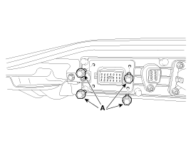
Disconnect the BMS ECU connector (A).
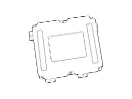
Loosen the mounting nut and remove the BMS ECU (A).
BMS ECU nut: 7.8 - 11.8 N·m
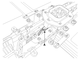
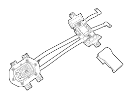
Disconnect the service plug interlock connector (A).
Loosen the nut (A) and remove the service plug cable assembly (B). Service plug cable assembly nut: 7.8 - 11.8 N·m
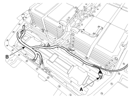
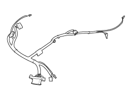
Loosen the mounting bolt (A) and remove the BMS extension wiring (B).
Ground bolt: 7.8 - 11.8 N·m
Service Plug Cable
Refer to High Voltage Battery Management System - Service Plug - "Service Plug Cable".
Front Body Panel, Left
Remove the Power Relay Assembly (PRA). (Refer to High-Voltage Battery System - Power Relay Assembly).
Remove the front body panel, left.
Service Plug Bracket
Disable the high voltage. (Refer to High-Voltage Battery Control System - High-Voltage Disable Procedure).
Loosen the mounting bolt (A) and remove the service plug bracket (B).
High-Voltage Connector Assembly
Remove the high-voltage battery case upper part. (Refer to High-Voltage Battery System - Case - Upper Case).
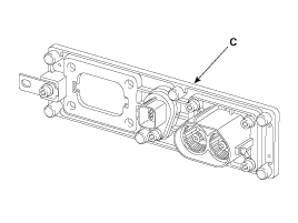
After disconnecting the interlock switch connector (A) and loosening the mounting bolt (B), remove the high-voltage connector (C). High-voltage connector mounting bolt: 7.8 - 11.8 N·m
Rear Battery Mounting Bracket
Remove the high-voltage battery case upper part. (Refer to High-Voltage Battery System - Case - Upper Case).
Loosen the mounting nut and remove the battery module outlet duct (A). Battery module outlet duct mounting nut: 7.8 ~ 11.8 N·m
Loosen the mounting bolt (A) and remove the bracket (B). Rear battery mounting bracket bolt: 7.8 - 11.8 N·m
Waterproof Rain Cover Bracket
Remove the high-voltage battery pack assembly. (Refer to High-Voltage Battery System - Repair Procedures - Removal).
Loosen the mounting bolt and nut and remove the waterproof rain cover bracket (A).
Rear Mounting Bracket, High-Voltage Battery System
Raise the vehicle.
Loosen the bolt (A) of the rear mounting bracket of the high-voltage battery system. Rear mounting bracket bolt, high-voltage battery system: 54.9 - 82 N·m
Remove the rear mounting bracket of the high-voltage battery system (A).
Battery Voltage and Temperature Sensor Harness
Remove the high-voltage battery assembly. (Refer to High-Voltage Battery System - High-Voltage Battery Assembly).
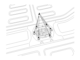
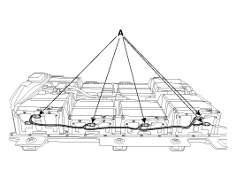
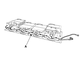
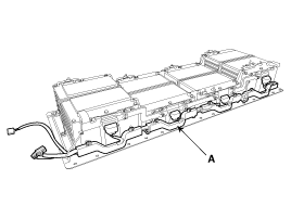
Loosen the harness clamp screw and remove the voltage and temperature harness (A) from the high-voltage battery assembly. [Left][RH]
Positive (+) High-Voltage Power Cable
Remove the high-voltage battery case upper part. (Refer to High-Voltage Battery System - Case - Upper Case).
Disconnect the high-voltage power cable cover (A).
Loosen the mounting nut and disconnect the positive (+) high-voltage power cable (A). Positive (+) high-voltage power cable nut: 7.8 - 11.8 N·m
High-Voltage Negative (-) Power Cable
Remove the high-voltage battery case upper part. (Refer to High-Voltage Battery System - Case - Upper Case).
Disconnect the high-voltage power cable cover (A).
Loosen the mounting nut and disconnect the negative (-) high-voltage power cable (A). Negative (-) high-voltage power cable nut: 7.8 - 11.8 N·m
Battery Module Output Channel
Remove the high-voltage battery case upper part. (Refer to High-Voltage Battery System - Case - Upper Case).
Loosen the mounting nut and remove the battery module outlet duct (A). Battery module outlet duct mounting nut: 7.8 ~ 11.8 N·m
Protective Plug
Refer to High Voltage Battery Management System - "Service Plug".
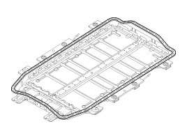
High-Voltage Battery Case Lower Part
Refer to High Voltage Battery System - Case - "Lower Case".
High-Voltage Battery Case Upper Part
Refer to High Voltage Battery System - Case - "Upper Case".
Installation
Be sure to read and observe the "General Safety Information and Caution" before performing any work on the high voltage system. Failure to follow the safety instructions may result in serious electrical injury.
Before performing any work, be sure to disconnect high voltage related to the high voltage system (refer to "High Voltage Disconnection Procedure"). Failure to follow safety instructions may result in serious electric shock.
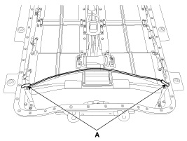
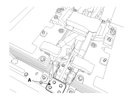
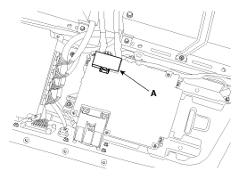
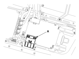
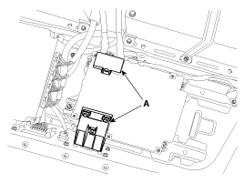
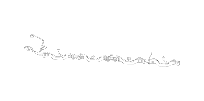
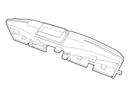
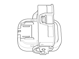
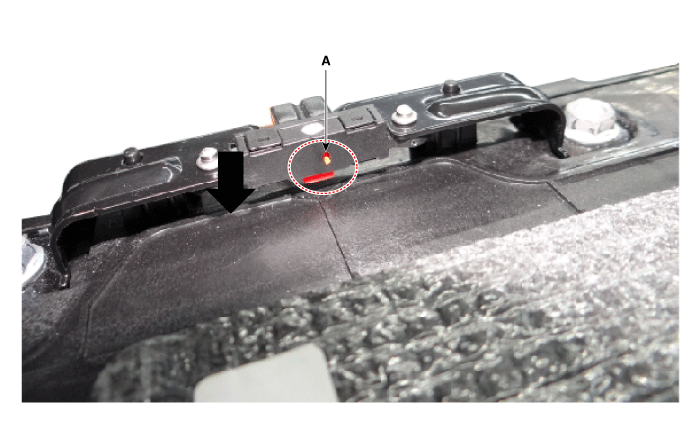
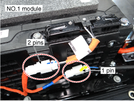
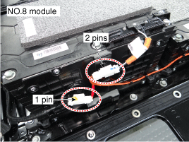
When installing the RAD harness, be sure to check the connector installation. [If incorrect] 1. Precharge failure. 2. RAD malfunction (incorrectly detects that the high-voltage battery is swollen). [Main inspection points] 1. Make sure the RAD switch is facing down.2. Be careful not to reverse the RAD module battery No. 1 connector (2 pins) and the BMS extension connector (1 pin) during assembly.3. Be careful not to reverse the RAD module battery No. 8 connector (2 pins) and the BMS extension connector (1 pin) during assembly.
Replacement [Rear Seat Back Assembly] 1. Disconnect the lower rear seat belt anchor (C) by pressing the stopper pin (B) of the center mini buckle (A) with a flat-tip screwdriver. 2. Fold the rear seat back assembly forward. 3. Remove the center hinge cover (A). 4. Loosen the rear seat back mounting bolt (A)...
Replacement • Be sure to read and follow the "General Safety Information and Caution" before performing any work on the high voltage system. Failure to follow instructions may result in serious electrical injury. • Be...
?
Test yourself
A quick Kia Soul EV Owner's Manual quiz: every answer comes with an explanation and a link to the manual page.



















 Inspection
 Battery Specifications