Electric Vehicle Battery System
Inspection
In this manual: Electric Vehicle Battery System
27steps
~162min
4/5difficulty
Done 0 of 27
Inspection
|

|
[High Voltage Battery Pack Assembly Inspection]
| Specification | Method | Countermeasure | ||
| Disconnection | - | Visual inspection | - | |
| Rust | ||||
| Discoloration | ||||
| Installation Status | ||||
| Leakage | ||||
| BMS ECU DTC | Refer to the Trouble Code Troubleshooting manual | Refer to the Trouble Code Troubleshooting manual | Refer to the Trouble Code Troubleshooting manual | |
| SOC | 5% ~ 95% | Check the "Current Data" using GDS | Refer to "SOC Level and Countermeasures". | |
| Voltage | Cell | 2.5 ~ 4.3 V | Check the "Current Data" using GDS | Check the battery voltage sensor circuit (Refer to "Battery Voltage Measurement Circuit"). |
| Pack | 240 ~ 413 V | |||
| Cell Voltage Deviation |
Less than 40 mV | |||
| Insulation resistance | 300 kΩ ~ 1000 kΩ | Check the "Current Data" using GDS | Refer to "Insulation Resistance Circuit". | |
| More than 2 MΩ | Using a Megohmmeter | |||
| More than 2 MΩ | Using a Megohmmeter | |||
[Visual Inspection]
Item - Electrical system, cooling system, high voltage battery pack assembly. Problem - Disconnection, rust, component condition, oil leak[SOC Inspection]
- Turn the ignition OFF.
- Connect GDS to the DLC.
- Turn the ignition on.
- Check the SOC in the GDS service data.
SOC: 5 ~ 95 %

[Battery Voltage Inspection]
- Turn the ignition OFF.
- Connect GDS to the DLC.
- Turn the ignition on.
- Check the Cell Voltage and Pack Voltage in the GDS service data. Cell Voltage: 2.5 ~ 4.3 V Pack Voltage: 240 ~ 413 V Cell Voltage Deviation: Less than 40 mV
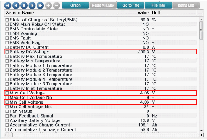
[Voltage Measurement Circuit Inspection]
- Remove the high voltage battery assembly. (Refer to High Voltage Battery System - "Battery Assembly")
- Disconnect the voltage and temperature sensor harness. (Refer to High Voltage Battery System - Repair Procedures - Removal - "Voltage and Temperature Sensor Harness".)
- Perform a continuity inspection of the battery module and BMS ECU connector.
Specified value: Less than 1 Ω (20°C)
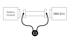
- Place the BMS ECU in the lower case.
- Connect the voltage and temperature sensor harness to the BMS ECU.
- Measure the insulation resistance between the battery module harness and the lower case.
Specified value: More than 1 MΩ (20°C)
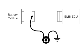
[Insulation Resistance Inspection (Vehicle)]
The insulation condition between the vehicle and the battery can be checked using GDS or resistance measurement. [GDS - Service Data]- Turn the ignition off.
- Connect GDS to the DLC.
- Turn the ignition on.
- Check the insulation resistance in the GDS service data.
Specified value: 300 kΩ ~ 1000 kΩ
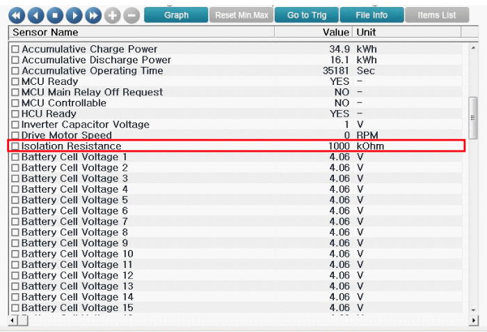
- Disconnect high voltage. (Refer to High Voltage Battery Management System - "High Voltage Disconnection Procedure")
- Connect the negative (-) lead of the megohmmeter (A) to the vehicle body ground.
For accurate measurement, connect the negative (-) lead to unpainted parts.
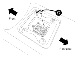
- After connecting the positive (+) terminal to the battery positive (+) terminal, measure the resistance as follows. [Insulation Resistance of Battery Pack Positive (+) Terminal]
- Apply 500 V with the megohmmeter, then wait approximately 1 minute to measure a stable resistance value.
- Check the resistance.
Specified value: more than 2 MΩ (20°C)
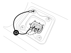
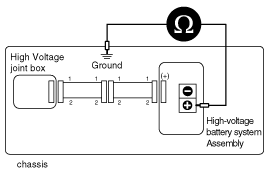
- After connecting the positive (+) terminal to the battery negative (-) terminal, measure the resistance as follows. [Insulation Resistance of Battery Pack Negative (-) Terminal]
- Apply 500 V with the megohmmeter, then wait approximately 1 minute to measure a stable resistance value.
- Check the resistance.
Specified value: More than 2 MΩ (20°C)
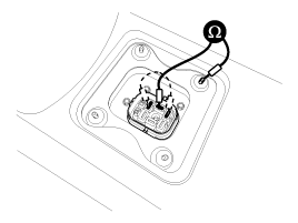
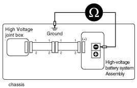
[Insulation Resistance Inspection (Battery)]
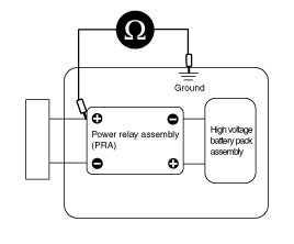
[Using a megohmmeter]- Remove the high voltage battery assembly. (Refer to High Voltage Battery System - "Battery Assembly")
- Remove the high voltage battery upper case assembly. (Refer to High Voltage Battery System - Case)
- Remove the protective cover (A) of the Power Relay Assembly (PRA).
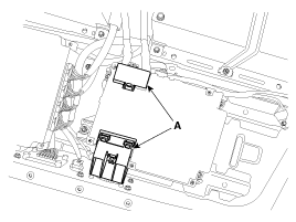
- Connect the negative (-) lead of the megohmmeter to the lower case.
For accurate measurement, connect the negative (-) lead to unpainted parts.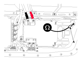
- Connect the positive (+) lead to the high voltage battery terminals to measure the resistance. [Insulation Resistance of High Voltage PRA Positive (+) Terminal]
- Connect the positive (+) lead of the megohmmeter (A) to the PRA high voltage positive (+) terminal.
- Apply 500 V with the megohmmeter, then wait approximately 1 minute to measure a stable resistance value.
- Check the resistance value.
Specified value: more than 2 MΩ (20°C)

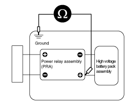
- Connect the positive (+) lead of the megohmmeter (B) to the PRA high voltage negative (-) terminal.
- Apply 500 V with the megohmmeter, then wait approximately 1 minute to measure a stable resistance value.
- Check the resistance value.
Specified value: more than 2 MΩ (20°C)
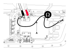
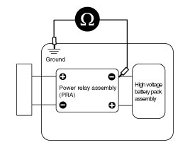
- Connect the positive (+) lead of the megohmmeter (A) to the PRA inverter power positive (+) terminal.
- Apply 500 V with the megohmmeter, then wait approximately 1 minute to measure a stable resistance value.
- Check the resistance value.
Specified value: more than 2 MΩ (20°C)
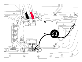
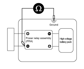
- Connect the positive (+) lead of the megohmmeter (A) to the PRA inverter power negative (-) terminal.
- Apply 500 V with the megohmmeter, then wait approximately 1 minute to measure a stable resistance value.
- Check the resistance value.
Specified value: more than 2 MΩ (20°C)

Test yourself
A quick Kia Soul EV Owner's Manual quiz: every answer comes with an explanation and a link to the manual page.
Was this page helpful?