SRS Control Module (SRSCM)
Description and Operation
Description
The main purpose of the SRSCM (Supplemental Restraint System Control Module) is to distinguish between an event that requires deployment of the restraint system and an event that does not. The SRSCM must decide whether or not to deploy the restraint system. When it determines that pretensioners and/or airbag deployment are required, the SRSCM must supply sufficient power to the pretensioners and airbag inflators to start deployment.
The SRSCM determines that an impact may require deployment of the pretensioners and airbags based on data received from the impact sensors and other components in combination with the safing function.
The SRSCM will not be ready to detect a crash or activate the restraint devices until the signals in the SRSCM circuit stabilize.
The SRSCM may be able to activate the restraint devices within approximately 2 seconds, but full operation is guaranteed only after the check is completed.
The SRSCM must perform a diagnostic procedure and turn on the SRS indicator when the ignition is turned on. The system must perform a continuous diagnostic procedure and issue a warning via the warning lamp when a malfunction is detected. Also, the serial diagnostic communication interface will be used to facilitate servicing of the restraint system control unit.
Components and Component Location
Components

| 1. Supplemental Restraint System Control Module (SRSCM) |
Repair Procedures
Removal
Disconnect the negative battery cable and wait at least thirty seconds before starting work.
Remove the floor console assembly.
(Refer to Body - Floor Console Assembly)
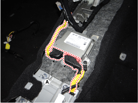
Disconnect the Supplemental Restraint System Control Module (SRSCM) connector (A).
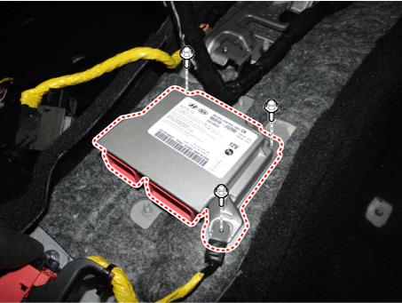
Loosen the bolt and nuts, then remove the supplemental restraint system control module (SRSCM).
Installation
Remove the ignition key from the vehicle.
Disconnect the negative battery cable and wait at least thirty seconds before starting work.
Install the SRSCM using the SRSCM mounting bolt and nuts.
Tightening Torque: 9.4–13.5 N·m
Connect the SRSCM wiring harness connector.
Install the floor console assembly.
(Refer to Body - Floor Console Assembly)
Connect the battery negative cable.
After installing the SRSCM, check that the system operates correctly:
Turn the ignition ON. The SRS indicator should illuminate for approximately six seconds, then turn off.
Variant Coding
After replacing the SRSCM, perform Variant Coding.
Variant Coding Procedure
■ Online Method with KDS
Turn the ignition OFF and connect the KDS.
With the ignition ON and the engine OFF, select the vehicle name and the airbag system.
Select the variant coding mode.
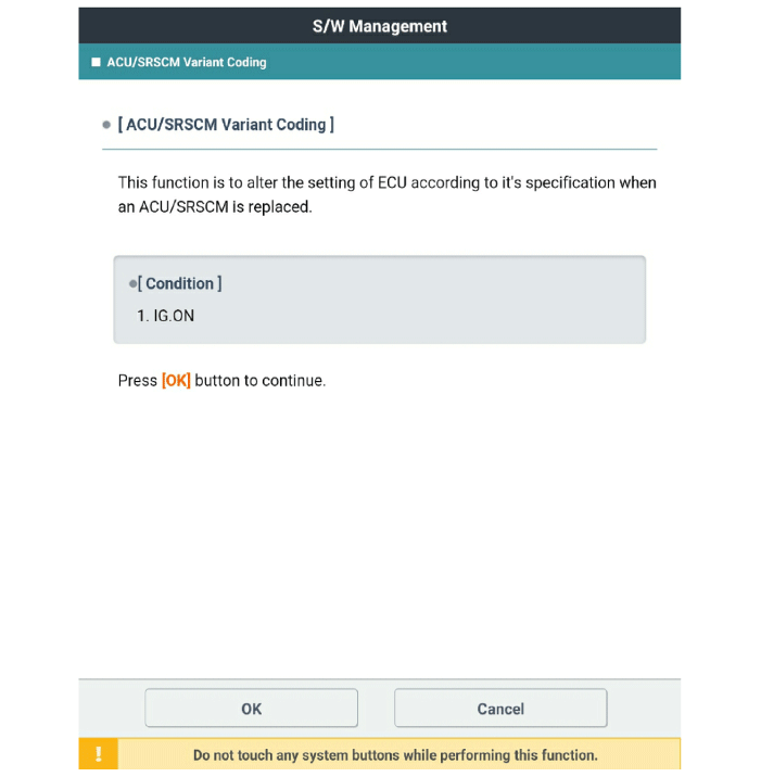
Follow the on-screen instructions as shown below.
1) Initial ACU Option Coding
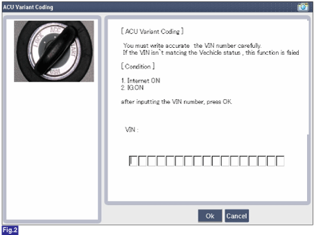
2) Enter VIN
3) Process Option Coding - 1
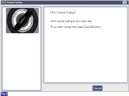
4) Process Option Coding - 2

5) Option Coding Completed
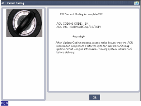
■ Offline Method with KDS (When Internet Connection Is Not Available)
1) Initial ACU Option Coding
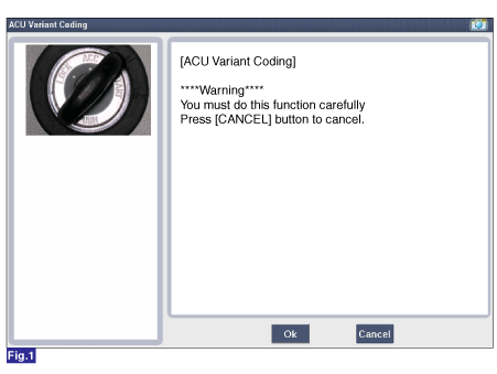
2) Enter ACU coding code
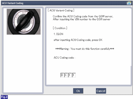
3) Recheck the ACU coding code.
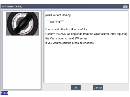
4) Process Option Coding - 1
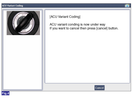
5) Process Option Coding - 2

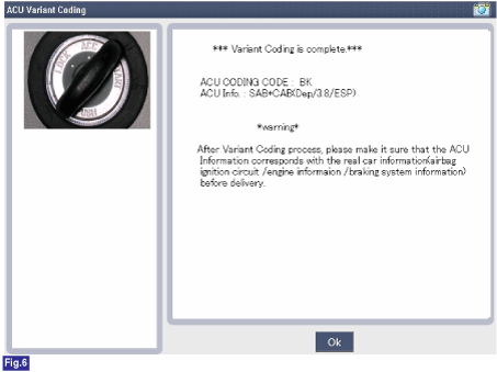
6) Variant coding completed
Test yourself
A quick Kia Stinger CK quiz: every answer comes with an explanation and a link to the manual page.