Brake booster
Components and Component Location
Components
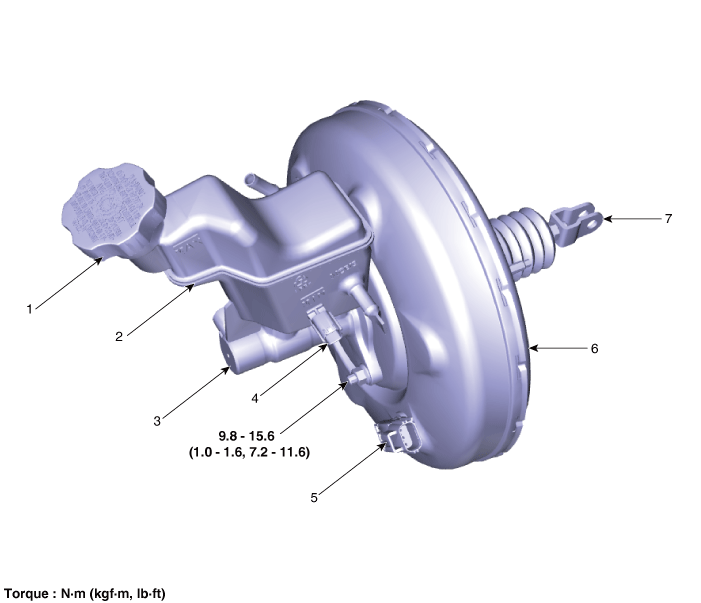
| 1. Reservoir Cap 2. Reservoir 3. Master Cylinder 4. Brake Fluid Level Sensor |
5. Vacuum Sensor 6. Brake Booster 7. Push Rod |
Repair Procedures
Brake Booster Operation Test
To perform a simple check of brake booster operation, carry out the following inspections.
Start the engine, let it run for one to two minutes, then stop it. If the pedal initially falls fully but gradually rises higher in subsequent attempts, the booster is operating normally. If the pedal height remains unchanged, the booster is not operating.
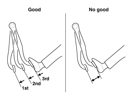
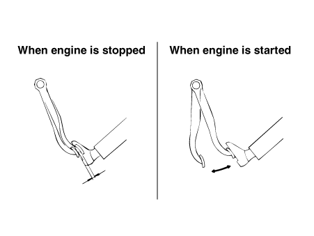
With the engine stopped, depress the brake pedal several times.
Then depress the brake pedal and start the engine. If the pedal moves slightly downward, the booster is in good condition. If there is no change, the booster is not operating.
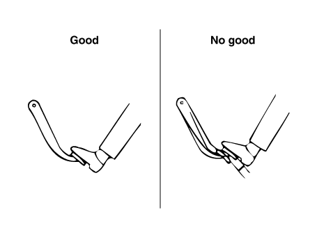
With the engine running, depress the brake pedal and stop the engine. Hold the pedal depressed for 30 seconds. If the pedal height does not change, the booster is in good condition. If the pedal rises, the booster is not operating.
If the above three tests are satisfied, the booster performance can be judged to be in good condition.
If any one of the three tests above is unsatisfactory, inspect the check valve, vacuum hose, and booster for malfunction.
Removal
Turn the ignition switch OFF and disconnect the negative (-) battery cable.
Remove the air cleaner assembly.
G 2.0 NU MPI (Refer to Engine Mechanical System — "Air Cleaner")
G 2.5 GDI THETA II (Refer to Engine Mechanical System — "Air Cleaner")
Remove the battery.
G 2.0 NU MPI (Refer to Engine Electrical System - "Battery")
G 2.5 GDI THETA II (Refer to Engine Electrical System - "Battery")
Remove the ECM bracket assembly.
G 2.0 NU MPI (Refer to Engine Control/Fuel System — "Engine Control" — "Engine Control Module (ECM)")
G 2.5 GDI THETA II (Refer to Engine Control/Fuel System — "Engine Control" — "Engine Control Module (ECM)")
Remove the master cylinder.
(Refer to Brake System - "Master Cylinder")
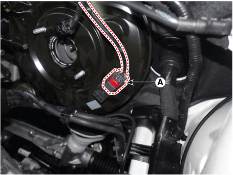
Disconnect the brake booster vacuum pressure sensor connector (A).
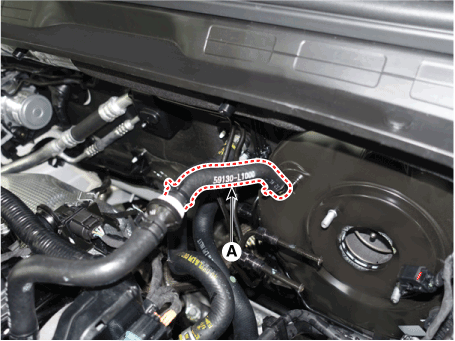
Remove the clip and vacuum hose (A) from the brake booster.
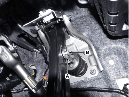
Remove the lock pin (A) and the flat head pin (B).
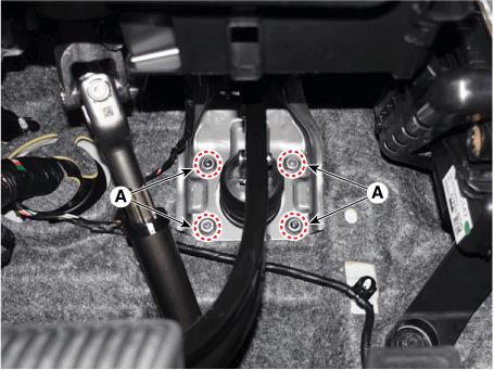
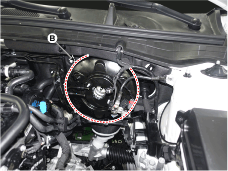
Loosen the lock nut (A) and remove the brake booster (B).
Tightening torque: 12.7–17.6 N·m
Inspection
Inspect the vacuum hose.
Check the boot for damage.
Installation
Install in the reverse order of removal.
After installation, bleed the brake system.
(Refer to Brake System - "Brake Bleeding Procedures")
Check for brake fluid leakage and pedal condition.
Test yourself
A quick Kia Optima DL3 quiz: every answer comes with an explanation and a link to the manual page.