Joint Assembly (Wheel Side)
Components and Component Location
Components
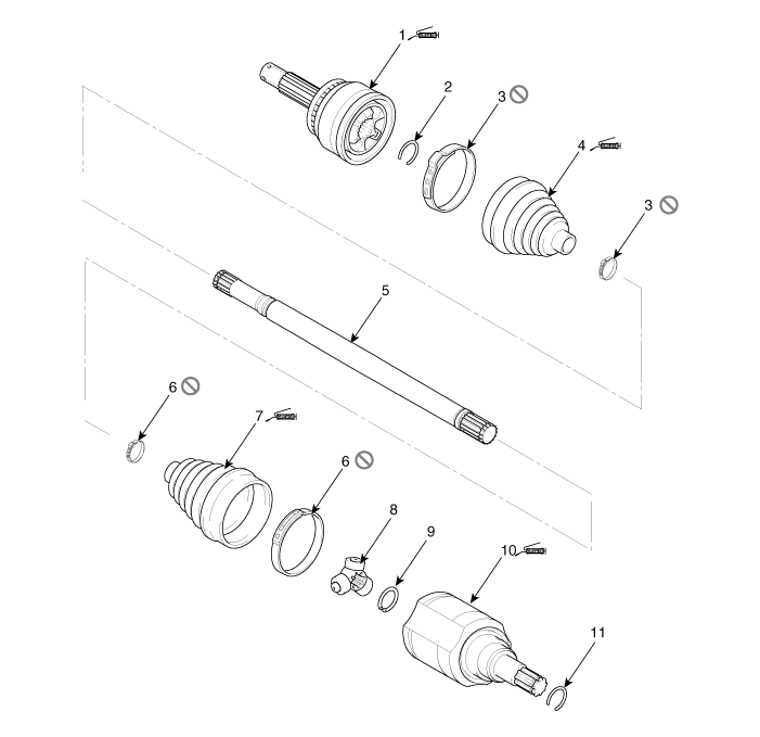
| 1. Wheel Side Joint Assembly 2. Wheel Side Snap Ring 3. Wheel Side Boot Band 4. Wheel Side Boot |
5. Shaft 6. Transaxle Side Boot Band 7. Transaxle Side Boot 8. Spider Assembly |
9. Snap Ring 10. Transaxle Side Joint Housing 11. Snap Ring |
Repair Procedures
Removal
Remove the front drive shaft.
(Refer to Drive Shaft Assembly — "Front Drive Shaft")
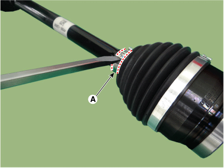
Use a (-) screwdriver to remove the small diameter boot band (A).
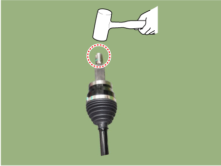
Using a plastic hammer, tap the upper part of the joint spline 2-3 times.
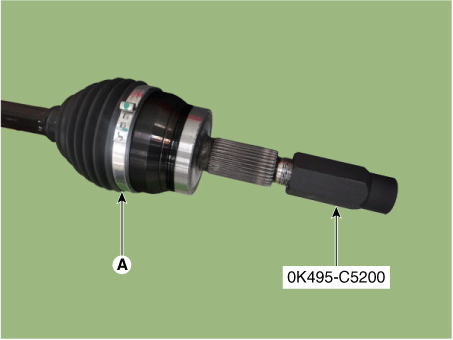
Install the SST (0K495-C5200) onto the drive shaft spline (A).
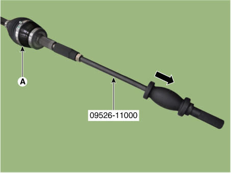
After securing the drive shaft in a vise, remove the joint assembly (A) using the SST (09526-11000).
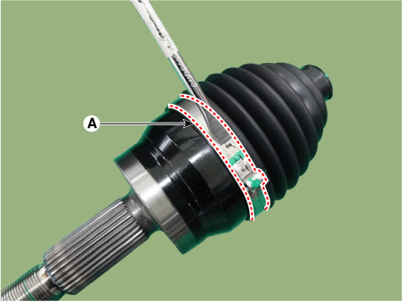
Use a (-) screwdriver to remove the large diameter boot band (A).
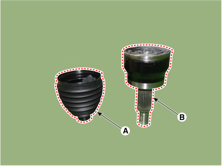
Remove the joint boot (A) and joint assembly (B).
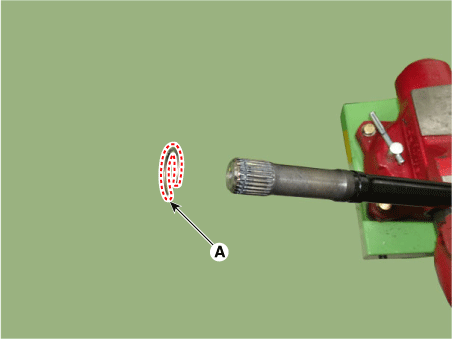
Remove the snap ring (A) from the drive shaft.
Inspection
Check the splines (A) for damage, wear, or cracks.
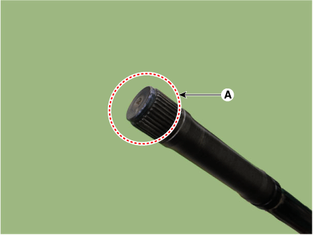
Check the boot for water or foreign material.
Check the joint assembly for damage, wear, cracks, and rust.
Replace any defective parts.
Installation
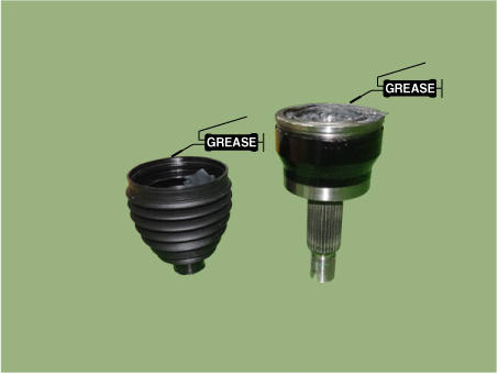
Apply the specified grease to the joint housing and boot.
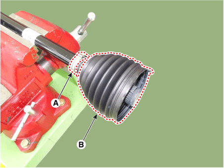
Install the band (A) and boot (B) onto the drive shaft from the wheel side.
Insert the snap ring (A) into the joint.
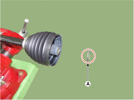
Insert the boot into the joint.
Using a plastic hammer, tap the upper part of the joint spline 2-3 times.
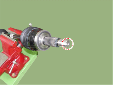
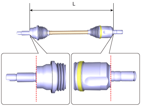
Set the drive shaft length to the standard value, then install the boot band to adjust the air in the wheel side boot.
Engine Distance (L) mm (in.) Left side Right Side THETA III 2.5 GDI 538,9 (21,2165) 835,5 (32,8937) NU 2.0 MPI 551 (21,6929) 824,3 (32,4527)
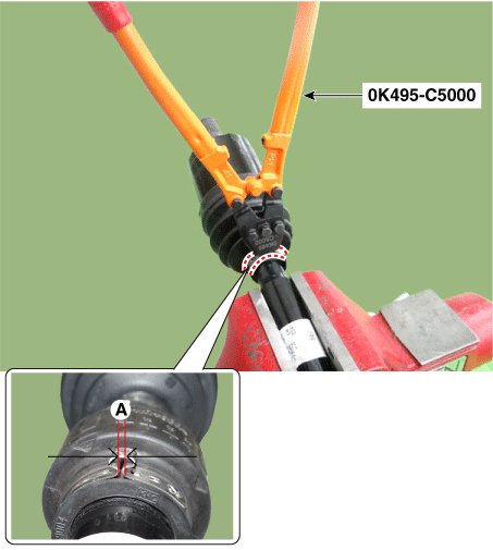
Install the small diameter boot band using the SST (0K495-C5000).
Clearance (A): 2.0 mm (0.0787 in.) or less
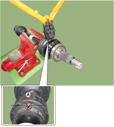
Install the large diameter boot band using the SST (0K495-C5000).
Clearance (A): 2.0 mm (0.0787 in.) or less
Install the front drive shaft.
(Refer to Drive Shaft Assembly — "Front Drive Shaft")
Inspect the front wheel alignment.
(See Suspension System - Alignment)
Test yourself
A quick Kia Optima DL3 quiz: every answer comes with an explanation and a link to the manual page.