Front Driveshaft
Components and Component Location
Components
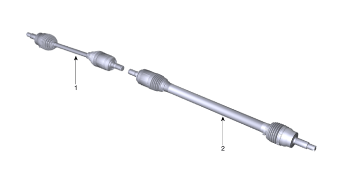
| 1. Front Drive Shaft (LH) | 2. Front Drive Shaft (RH) |
Repair Procedures
Removal
Disconnect the negative (-) battery cable.
Remove the front wheel and tire.
(See Suspension System — Wheel)
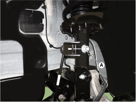
Disconnect the stabilizer bar link (A) from the strut assembly after loosening the nut.
Tightening torque: 98.0 - 118 N·m
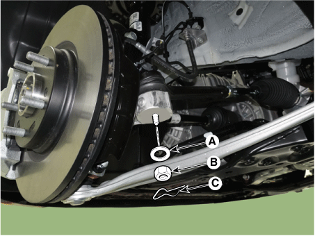
Disconnect the tie rod end ball joint from the steering knuckle using SST (09568-2J100).
Remove the cotter pin (C).
Remove the castle nut (B) and washer (A).
Tightening torque: 98.1 - 118 N·m
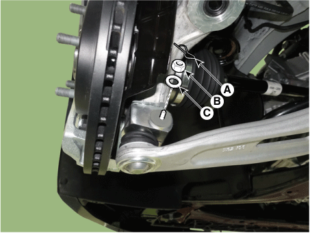
Disconnect the tie rod end ball joint from the steering knuckle using SST (09568-2J100).

Loosen the lower arm mounting nut (A).
Remove the stop pin (A).
Remove the lower arm mounting nut (B) and washer (C).
Tightening torque: 98.1 - 118 N·m
Disconnect the lower arm ball joint from the steering knuckle using SST (0K545-A9100).
After removing the bolts from the front steering knuckle, install and tighten the body bolt (A) at the bottom.
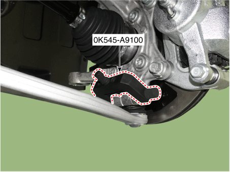
Insert the auxiliary body (B) between the front knuckle and the auxiliary body bolt.
Tighten the auxiliary body bolt (C) to increase the clearance of the front joint.

Install the safety wire and the main body (A) between the front strut and the lower arm.

After installing the body (A), turn the handle (B) clockwise to secure it to the lower arm with the clamp.
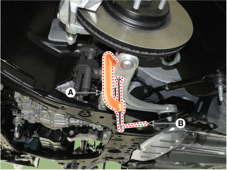
Slowly tighten the main body bolt (A) and separate the lower arm from the front joint.

Unstake the drive shaft hub nut lock by tapping a chisel with a hammer.
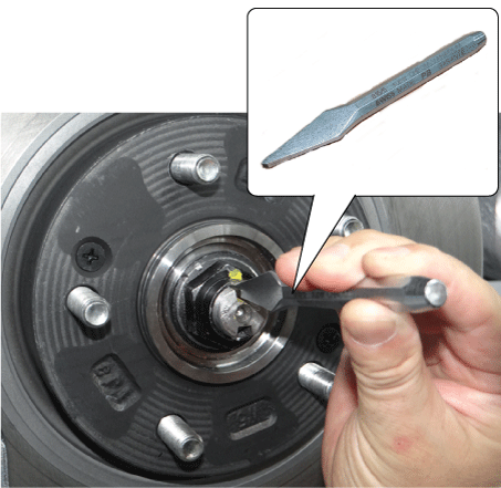
Remove the staked nut (A) from the front axle.
Tightening torque: 294.2–314 N·m

Disconnect the propeller shaft from the axle hub using SST (09517-4E000).

Disconnect the front drive shaft (A) from the steering knuckle assembly (B).
[LH]
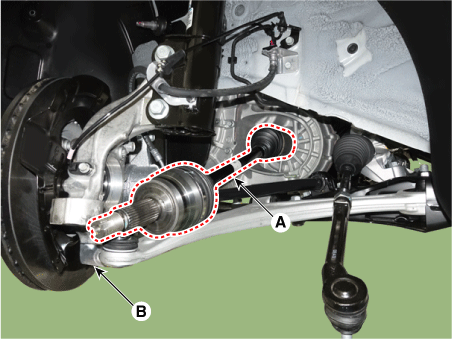
[RH]
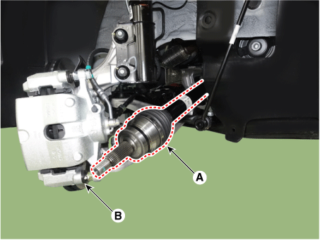
Remove the drive shaft (B) using a pry bar (A).
[LH]
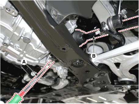
[RH]
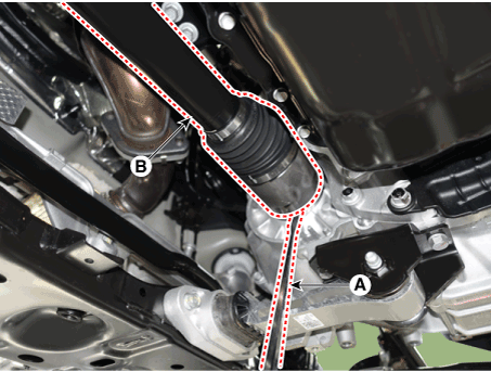
Installation
Install in the reverse order of removal.
Inspect the front wheel alignment.
(See Suspension System - Alignment)
Inspection
Inspect the drive shaft boots for damage and wear.
Inspect the drive shaft splines for wear or damage.
Make sure there is no water or foreign matter in the joint.
Inspect the spider assembly for roller rotation, wear, or corrosion.
Inspect the groove inside the joint case for wear or corrosion.
Inspect the dynamic damper for damage or cracks.
Test yourself
A quick Kia Optima DL3 quiz: every answer comes with an explanation and a link to the manual page.