Transmission Fluid Temperature Sensor (Main Wiring Harness)
Specifications
Specification
| Item | Specification |
| Type | *NTC thermistor |
| Temp. [(°C)°F] / Resistance (kΩ) | (-40)-40/48,1 |
| (-20)-4,0/15,6 | |
| (0)32,0 / 5,88 | |
| (20)68,0/2,51 | |
| (40)104,0/1,19 | |
| (60)140,0/0,61 | |
| (80)176,0/0,32 | |
| (100)212,0/0,18 | |
| (120)248,0/0,10 | |
| (140)284,0/0,06 | |
| (150)302,0/0,05 |
*NTC: Negative Temperature Coefficient
Description and Operation
Description
The sensor used is a thermistor (NTC), whose resistance changes with temperature.
When the TCM supplies approximately 5 V to the sensor, the sensor output value changes according to the ATF temperature.
The oil temperature sensor is installed on the valve body, integrated with the main suspension module.
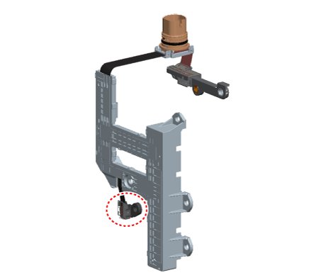
Functions
The transmission oil temperature sensor monitors the ATF temperature and sends the signal to the TCM.
The data from this sensor is used to determine the torque converter clutch activation and deactivation zones within the low and high temperature ranges, and to compensate the hydraulic pressure levels during gear shifting.
Components and Component Location
Components
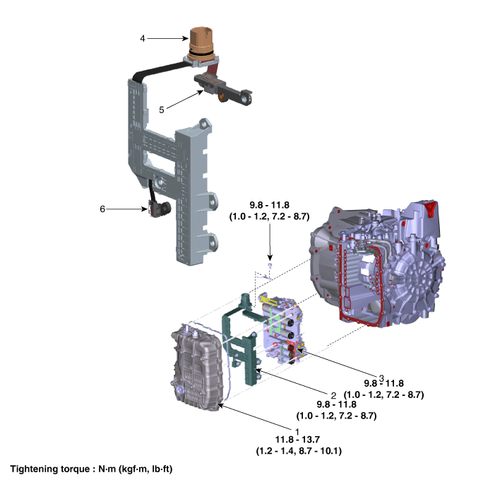
| 1. Valve Body Cover | 4. Main Connector |
| 2. Main Harness Assembly | 5. Speed Sensor Connector |
| 3. Valve Body | 6. Oil Temperature Sensor |
Repair Procedures
Inspection
The automatic transmission system can be quickly diagnosed for malfunctions using the Kia Diagnostic System (KDS). (Refer to the Diagnostic Trouble Code Manual.)
KDS provides the following information.
Self-diagnosis: Checks and displays diagnostic trouble codes (DTC).
Data list: Checks the input/output values of the system.
Active test: Checks the operating condition of the system.
Additional functions: System option control, zero point adjustment, and other functions.
Component Inspection
Check the resistance using KDS.
Item Specification Temp. [(°C)°F] / Resistance (kΩ) (-40)-40/48,1 (-20)-4,0/15,6 (0)32,0 / 5,88 (20)68,0/2,51 (40)104,0/1,19 (60)140,0/0,61 (80)176,0/0,32 (100)212,0/0,18 (120)248,0/0,10 (140)284,0/0,06 (150)302,0/0,05
Removal
Remove the under cover.
(Refer to Engine Mechanical System - "Engine Room Cover")
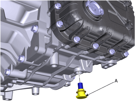
Remove the ATF drain plug (A), allow the fluid to drain, and then reinstall the drain plug.
Tightening torque: 33.3–43 N·m
Remove the air duct and air cleaner assembly.
(Refer to Engine Mechanical System - "Air Cleaner")
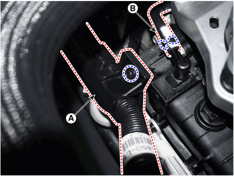
Remove the wire harness bracket (A) and breather hose (B).
Tightening torque: 9.8–11.8 N·m
Disconnect the hose (A) from the oil cooler hose clamp after draining the automatic transmission fluid.
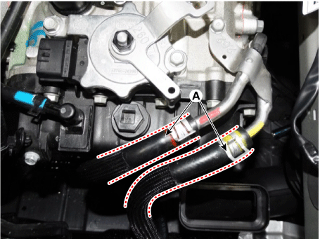
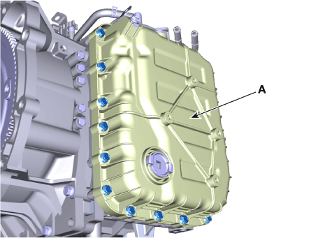
Raise the vehicle after loosening the upper valve body cover bolts.
Remove the valve body cover (A) by loosening the bolts.
Tightening torque: 11.8–13.7 N·m
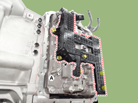
Remove the main harness assembly (A) after removing the bolts.
Tightening torque: 9.8–11.8 N·m
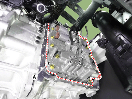
Remove the valve body (A) after loosening the bolts.
Tightening torque: 9.8–11.8 N·m
Disconnect the speed sensor connector (A).
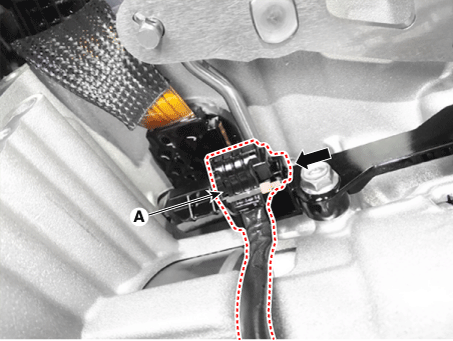
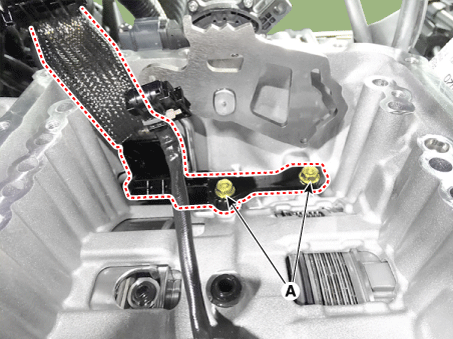
Loosen the main harness bolt (A).
Tightening Torque: 9.8–11.8 N·m
Disconnect the solenoid valve connector (A).
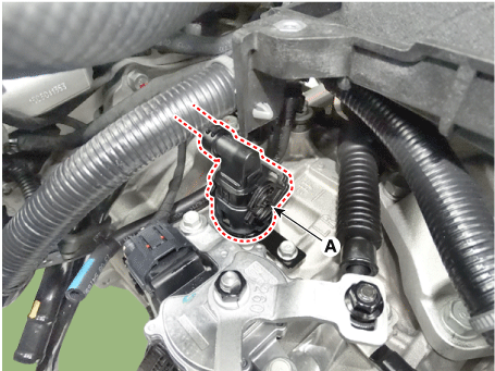
Remove the mounting clip of the solenoid valve connector (A).
Tightening torque: 9.8–11.8 N·m
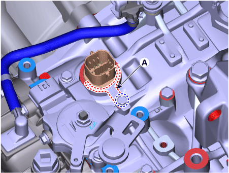
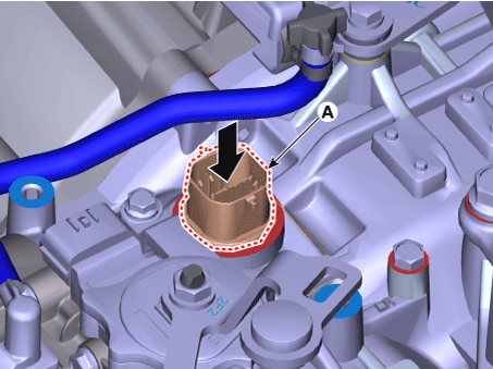
Disconnect the solenoid valve connector (A) by pressing down from the transaxle.
Installation
Install in the reverse order of removal.
Test yourself
A quick Kia Optima DL3 quiz: every answer comes with an explanation and a link to the manual page.