Engine Mechanical System
Cylinder block
In this manual: Engine Mechanical System
36steps
~221min
5/5difficulty
1special tools
Done 0 of 36
Repair Procedures
Disassembly
- Remove the engine and transaxle assembly. (Refer to Engine and Transaxle Assembly - "Engine and Transaxle Assembly")
- Remove the transaxle assembly from the engine assembly. (See Manual Transaxle System - Manual Transaxle)
- Remove the flywheel. (Refer to Cylinder Block Assembly - "Flywheel")
- Remove the rear oil seal. (Refer to Cylinder Block Assembly - "Rear Oil Seal")
- Install the engine assembly on an engine stand for disassembly.
- Remove the cylinder head cover. (Refer to Cylinder Head Assembly - Cylinder Head Cover)
- Remove the thermostat housing. (Refer to Cooling System - "Thermostat")
- Remove the timing chain. (Refer to Valve Timing System - Timing Chain)
- Remove the intake manifold. (Refer to Intake and Exhaust Systems — Intake Manifold)
- Remove the turbocharger manifold module. (Refer to Intake and Exhaust System - "Turbocharger Manifold Module")
- Remove the cylinder head. (Refer to Cylinder Head Assembly - "Cylinder Head")
- Remove the oil pan and oil screen. (Refer to Lubrication System - "Oil Pan")
- Remove the ladder frame (A). Insert a SST (09215-3C000) blade between the cylinder block and the ladder frame and cut the applied sealant. Then remove the ladder frame.
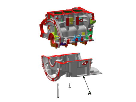
- Inspect the connecting rod side clearance. (See Cylinder Block Assembly - Piston and Connecting Rod)
- Check the connecting rod cap oil clearance. (Refer to Cylinder Block Assembly - Piston and Connecting Rod)
- Remove the piston and connecting rod assembly. (See Cylinder Block Assembly - Piston and Connecting Rod)
- Inspect the main bearing oil clearance. (See Cylinder Block Assembly - Crankshaft)
- Inspect the crankshaft end play. (See Cylinder Block Assembly - Crankshaft)
- Remove the crankshaft. (See Cylinder Block Assembly - Crankshaft)
- Remove the water jacket spacer. (Refer to Cylinder Block - Water Jacket Spacer)
- Remove the oil jet (A).
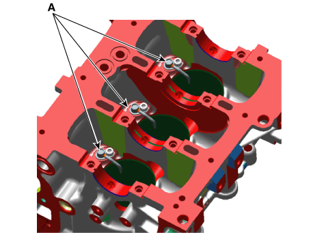
Inspection
- Remove the gasket material. Using a gasket scraper, remove all gasket material from the upper surface of the cylinder block.
- Clean the cylinder block. Using a soft brush and solvent, thoroughly clean the cylinder block.
- Inspect the cylinder block upper surface for flatness. Using a precision straightedge and feeler gauge, measure the surface contacting the cylinder head gasket for distortion. Cylinder block gasket surface flatness. Standard: less than 0.05 mm (0.002 in.). Limit: less than 0.02 mm (0.0008 in.) / 100 x 100 mm (3.937 x 3.937 in.)
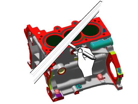
- Inspect the cylinder bore. Visually check the cylinder for vertical scratches. If deep scratches are found, replace the cylinder block.
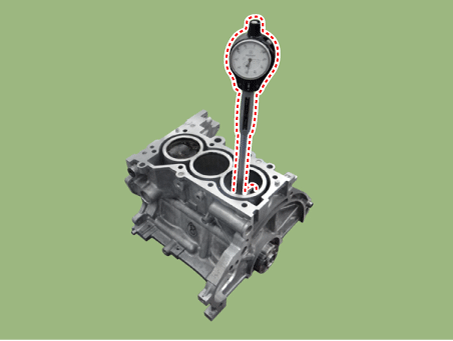
- Check the cylinder bore diameter. Using a cylinder gauge, measure the cylinder bore diameter at the positions in both the axial and transverse directions.
Standard diameter: 71.00–71.03 mm (2.7952–2.7964 in.)
Installation
- Install the oil jet (A).
Tightening torque: 8.8–12.7 N·m
- Install the water jacket spacer. (Refer to Cylinder Block - Water Jacket Spacer)
- Install the crankshaft. (Refer to Cylinder Block Assembly - Crankshaft)
- Inspect the crankshaft end play. (See Cylinder Block Assembly - Crankshaft)
- Inspect the main bearing oil clearance. (See Cylinder Block Assembly - Crankshaft)
- Install the piston and connecting rod assembly. (Refer to Cylinder Block Assembly - Piston and Connecting Rod)
- Check the connecting rod cap oil clearance. (Refer to Cylinder Block Assembly - Piston and Connecting Rod)
- Inspect the connecting rod side clearance. (See Cylinder Block Assembly - Piston and Connecting Rod)
- Install the oil pan frame.
- Using a gasket scraper, remove all old sealing material.
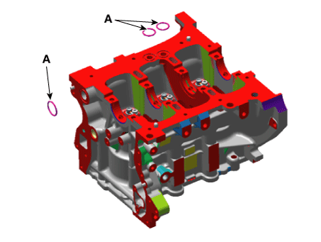
- Install the O-ring (A) on the cylinder block.
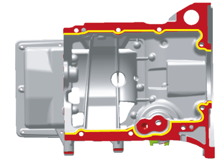
- Before assembling the ladder frame, apply liquid sealant to the ladder frame. Assemble the parts within 5 minutes after applying the sealant.
Bead width: 2.5–3.5 mm (0.1–0.14 in.)
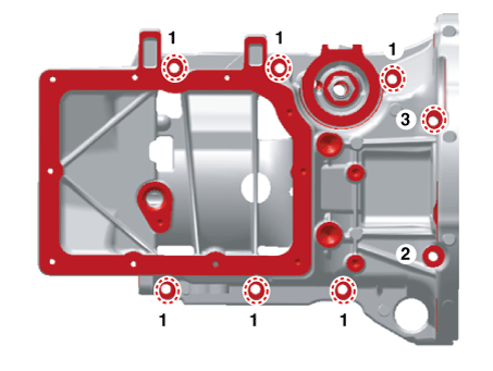
- Install and evenly tighten the ladder frame bolts in several passes.
Tightening torque: 28.4–32 N·m
- Assemble the remaining components in the reverse order of removal.
Test yourself
A quick Kia Picanto JA quiz: every answer comes with an explanation and a link to the manual page.
Was this page helpful?