Engine Mechanical System
Cylinder Head Assembly
In this manual: Engine Mechanical System
4steps
~24min
2/5difficulty
Done 0 of 4
Components and Component Location
Components
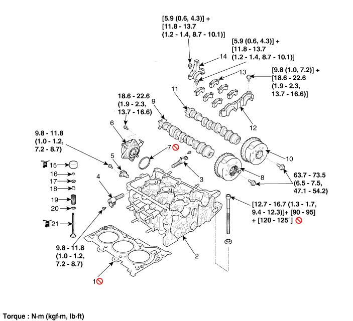
| 1. Cylinder Head Gasket 2. Cylinder Head 3. Intake Oil Control Valve (OCV) 4. Exhaust Oil Control Valve (OCV) 5. Exhaust Camshaft Position Sensor (CMPS) 6. Vacuum Pump 7. Vacuum Pump O-Ring |
8. Exhaust CVVT Assembly 9. Exhaust Camshaft 10. Intake CVVT Assembly 11. Intake Camshaft 12. Front Camshaft Bearing Cap 13. Center Camshaft Bearing Cap 14. Rear Camshaft Bearing Cap |
15. Mechanical Lash Adjuster (MLA) 16. Lock Clip 17. Retainer 18. Valve Stem Oil Seal 19. Valve Spring 20. Valve Spring Seat 21. Valve |
Repair Procedures
Valve Clearance Inspection and Adjustment
- Remove the cylinder head cover. (Refer to Cylinder Head Assembly - Cylinder Head Cover)
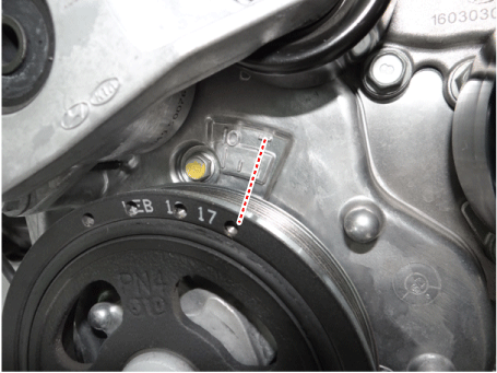
- Set the No. 1 cylinder to TDC/compression.
- Turn the crankshaft pulley and align its groove with the "T" timing mark on the timing chain cover and oil pump assembly.
- Check that the TDC marks of the intake CVVT sprocket and the exhaust camshaft sprocket are in a straight line with the cylinder head surface, as shown in the illustration. If not, turn the crankshaft one full revolution (360°).
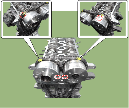
- Turn the crankshaft pulley and align its groove with the "T" timing mark on the timing chain cover and oil pump assembly.
- Inspect the valve clearance.
- Check only the specified valves (1st intake and 1st and 2nd exhaust valves). Measure the valve clearance.
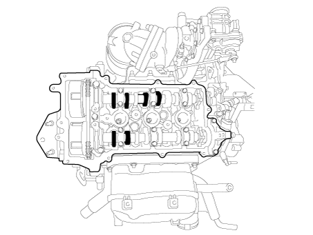
- Using a feeler gauge, measure the clearance between the tappet and the camshaft base circle.
- Record valve clearance measurements that do not meet specifications. They will be used later to determine whether replacement of the adjusting tappet is required.
- Turn the intake and exhaust camshafts 210° clockwise.
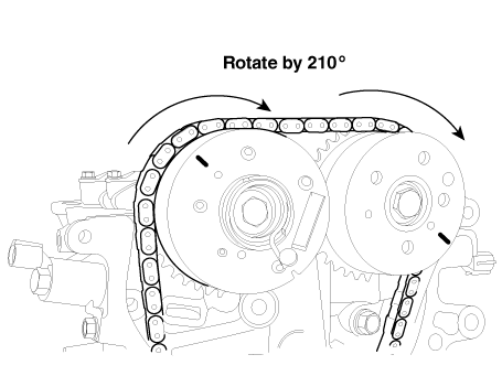
- Check only the specified valves (2nd and 3rd intake and 3rd exhaust). Measure the valve clearance.
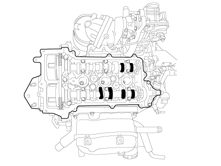
- Check only the specified valves (1st intake and 1st and 2nd exhaust valves). Measure the valve clearance.
- Adjust the intake and exhaust valve clearance.
- Set the No. 1 cylinder to TDC/compression.
- Remove the camshaft assembly. (Refer to Cylinder Head Assembly – "CVVT and Camshaft")
- Using a micrometer, measure the thickness of the removed tappet.
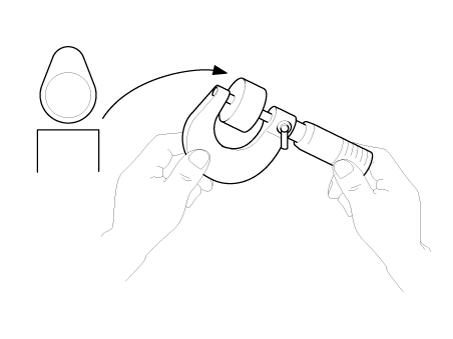
- Calculate the thickness of the new tappet so that the valve clearance meets the specified value. Valve clearance [Engine Coolant Temperature: 20 °C] T: Thickness of the removed tappet. A: Measured valve clearance. N: Thickness of the new tappet. Intake: N = T + [A - 0.2 mm (0.0079 in.)] Exhaust: N = T + [A - 0.25 mm (0.0098 in.)]
- Select a new tappet with a thickness as close as possible to the calculated value.
- After applying engine oil to the outer circumference and upper surface of the selected tappet, carefully insert the tappet into the cylinder head.
- Install the intake and exhaust camshafts. (Refer to Cylinder Head Assembly - "CVVT and Camshaft")
- Turn the crankshaft two revolutions in the normal direction of rotation (clockwise), then check that the TDC marks on the intake CVVT sprocket and the exhaust camshaft sprocket are in a straight line with the cylinder head surface.
- Recheck the valve clearance. Valve clearance [Engine Coolant Temperature: 20 °C] [Specification] Intake: 0.20-0.26 mm (0.0079-0.0102 in.) Exhaust: 0.39-0.45 mm (0.0154-0.0177 in.)
Test yourself
A quick Kia Picanto JA quiz: every answer comes with an explanation and a link to the manual page.
Was this page helpful?