Power Window Switch
Components and Component Location
Components
Driver Window Switch
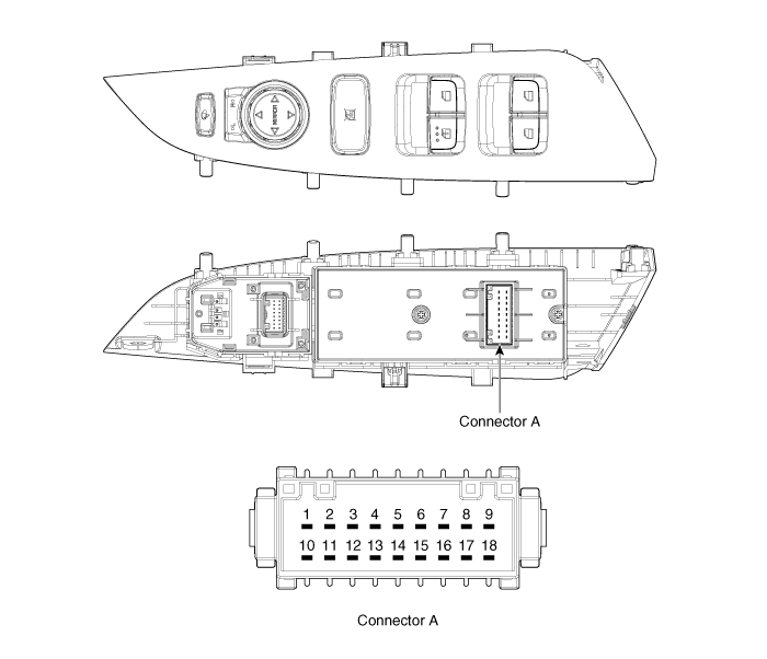
Connector Pin Information
[Front/Rear Driver Safety - Auto Up/Down]
[Left-hand drive]
| No. | Description | No. | Description |
| 1 | Front Right Window Regulator (Upper) | 10 | Rear Right Power Window Motor (Up) |
| 2 | - | 11 | Rear Right Power Window Motor (Down) |
| 3 | Front Right Power Window Motor (Down) | 12 | Battery (+)_RH |
| 4 | - | 13 | Rear Lamp |
| 5 | Left Window Lock Switch | 14 | Right Window Lock Switch |
| 6 | Driver's Main Power Window Switch (Up/Down) | 15 | Rear Left Power Window Motor (Up) |
| 7 | - | 16 | Rear Left Power Window Motor (Down) |
| 8 | Ground | 17 | - |
| 9 | - | 18 | Battery (+)_LH |
[Right-hand drive]
| No. | Description | No. | Description |
| 1 | - | 10 | Rear Right Power Window Motor (Up) |
| 2 | - | 11 | Rear Right Power Window Motor (Down) |
| 3 | - | 12 | Battery (+)_RH |
| 4 | - | 13 | Rear Lamp |
| 5 | Left Window Lock Switch | 14 | Right Window Lock Switch |
| 6 | Driver's Main Power Window Switch (Up/Down) | 15 | Rear Left Power Window Motor (Up) |
| 7 | Front Left Power Window Motor (Up) | 16 | Rear Left Power Window Motor (Down) |
| 8 | Ground | 17 | - |
| 9 | Front Left Power Window Motor (Down) | 18 | Battery (+)_LH |
[Driver Safety Front - Auto Up/Down]
[Left-hand drive]
| No. | Description | No. | Description |
| 1 | Front Right Window Regulator (Upper) | 10 | - |
| 2 | - | 11 | - |
| 3 | Front Right Power Window Motor (Down) | 12 | Battery (+)_RH |
| 4 | - | 13 | Rear Lamp |
| 5 | - | 14 | - |
| 6 | Driver's Main Power Window Switch (Up/Down) | 15 | - |
| 7 | - | 16 | - |
| 8 | Ground | 17 | - |
| 9 | - | 18 | - |
[Right-hand drive]
| No. | Description | No. | Description |
| 1 | - | 10 | - |
| 2 | - | 11 | - |
| 3 | - | 12 | - |
| 4 | - | 13 | Rear Lamp |
| 5 | - | 14 | - |
| 6 | Driver's Main Power Window Switch (Up/Down) | 15 | - |
| 7 | Front Left Power Window Motor (Up) | 16 | - |
| 8 | Ground | 17 | - |
| 9 | Front Left Power Window Motor (Down) | 18 | Battery (+)_LH |
[Front/Rear Auto Down]
[Left-hand drive]
| No. | Description | No. | Description |
| 1 | Front Right Window Regulator (Upper) | 10 | Rear Right Power Window Motor (Up) |
| 2 | - | 11 | Rear Right Power Window Motor (Down) |
| 3 | Front Right Power Window Motor (Down) | 12 | Battery (+)_RH |
| 4 | - | 13 | Rear Lamp |
| 5 | Left Window Lock Switch | 14 | Right Window Lock Switch |
| 6 | - | 15 | Rear Left Power Window Motor (Up) |
| 7 | Front Left Power Window Motor (Up) | 16 | Rear Left Power Window Motor (Down) |
| 8 | Ground | 17 | - |
| 9 | Front Left Power Window Motor (Down) | 18 | Battery (+)_LH |
[Right-hand drive]
| No. | Description | No. | Description |
| 1 | Front Right Window Regulator (Upper) | 10 | Rear Right Power Window Motor (Up) |
| 2 | - | 11 | Rear Right Power Window Motor (Down) |
| 3 | Front Right Power Window Motor (Down) | 12 | Battery (+)_RH |
| 4 | - | 13 | Rear Lamp |
| 5 | Left Window Lock Switch | 14 | Right Window Lock Switch |
| 6 | - | 15 | Rear Left Power Window Motor (Up) |
| 7 | Front Left Power Window Motor (Up) | 16 | Rear Left Power Window Motor (Down) |
| 8 | Ground | 17 | - |
| 9 | Front Left Power Window Motor (Down) | 18 | Battery (+)_LH |
[Front Auto Down]
[Left-hand drive]
| No. | Description | No. | Description |
| 1 | Front Right Window Regulator (Upper) | 10 | - |
| 2 | - | 11 | - |
| 3 | Front Right Power Window Motor (Down) | 12 | Battery (+)_RH |
| 4 | - | 13 | Rear Lamp |
| 5 | - | 14 | - |
| 6 | - | 15 | - |
| 7 | Front Left Power Window Motor (Up) | 16 | - |
| 8 | Ground | 17 | - |
| 9 | Front Left Power Window Motor (Down) | 18 | Battery (+)_LH |
[Right-hand drive]
| No. | Description | No. | Description |
| 1 | Front Right Window Regulator (Upper) | 10 | - |
| 2 | - | 11 | - |
| 3 | Front Right Power Window Motor (Down) | 12 | Battery (+)_RH |
| 4 | - | 13 | Rear Lamp |
| 5 | - | 14 | - |
| 6 | - | 15 | - |
| 7 | Front Left Power Window Motor (Up) | 16 | - |
| 8 | Ground | 17 | - |
| 9 | Front Left Power Window Motor (Down) | 18 | Battery (+)_LH |
Auxiliary Power Window Switches
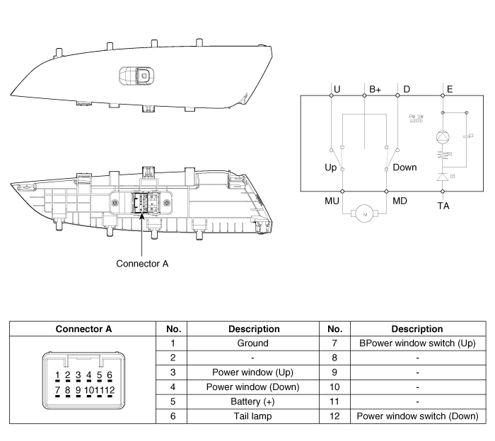
Rear Power Window Switch
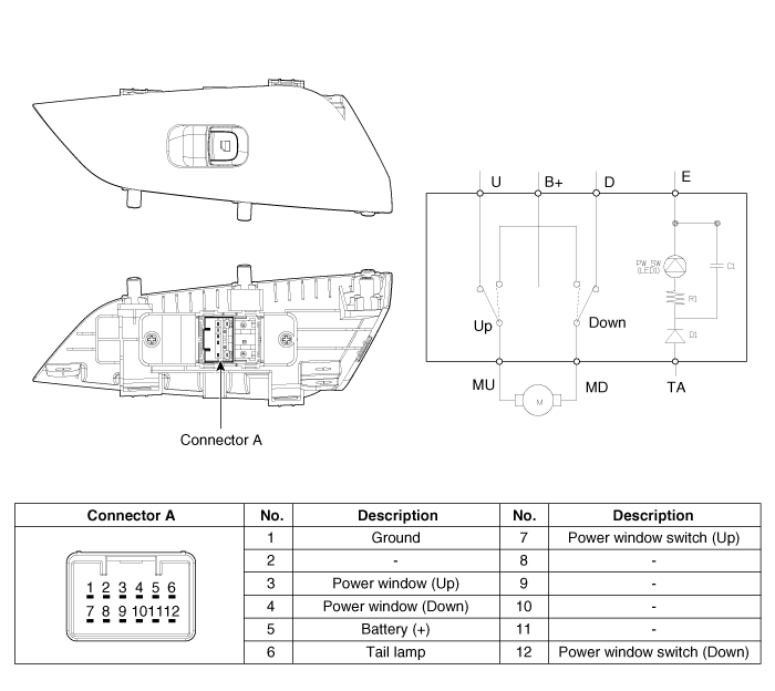
Repair Procedures
Removal
Driver Power Window Switch
Disconnect the negative (-) battery terminal.
Remove the front left door trim panel.
(Refer to Body - "Front Door Trim Panel")
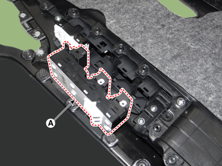
Remove the power window switch assembly (A) by pulling both ends of the switch holders (B).
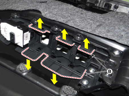
Auxiliary Window Regulator Switch
Disconnect the negative (-) battery terminal.
Remove the front right door trim panel.
(Refer to Body - "Front Door Trim Panel")
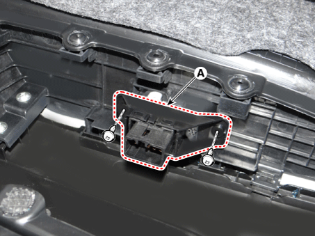
Loosen the mounting screws, then remove the power window switch assembly (A).
Rear Power Window Switch
Disconnect the negative (-) battery terminal.
Remove the rear door trim.
(Refer to Body - "Rear Door Trim Panel")
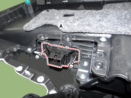
Loosen the mounting screws, then remove the power window switch assembly (A).
Installation
Driver Power Window Switch
Install the driver's power window switch.
Install the front door trim after connecting the connector.
Connect the negative (-) battery terminal.
Auxiliary Window Regulator Switch
Install the auxiliary power window switch.
Install the front door trim after connecting the connector.
Connect the negative (-) battery terminal.
Rear Power Window Switch
Install the rear power window switch.
Install the rear door trim after connecting the connector.
Connect the negative (-) battery terminal.
Inspection
Driver Power Window Switch
Disconnect the negative (-) battery terminal.
Remove the front left door trim panel.
Disconnect the power window switch connector from the door trim panel.
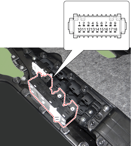
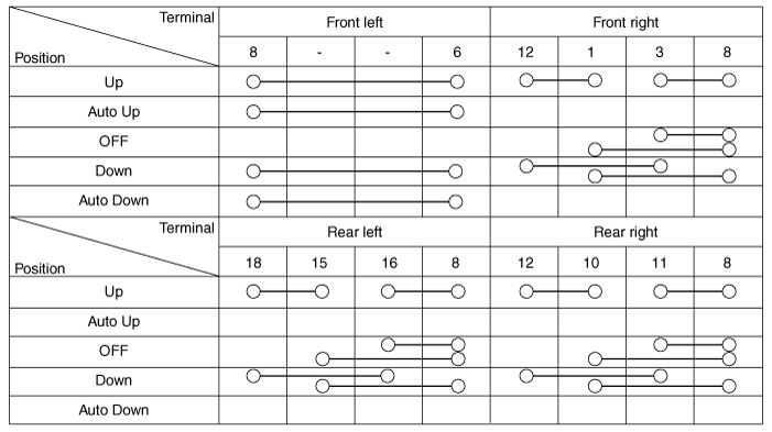
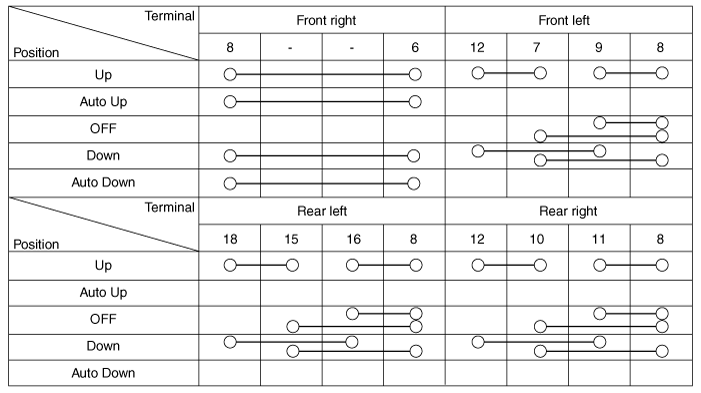
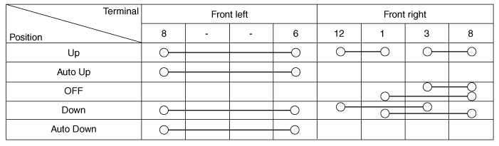
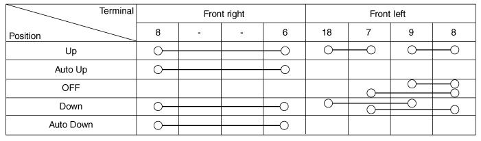
Check the continuity between the terminals at each switch position according to the table. If the continuity is not as specified, replace the switch.
[Front/Rear Driver Safety - Auto Up/Down]
(LHD)
(Right-Hand Drive)
[Front Driver Safety - Auto Up/Down]
(LHD)
(Right-Hand Drive)
[Front/Rear Auto Down]
(LHD)
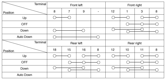
(Right-Hand Drive)
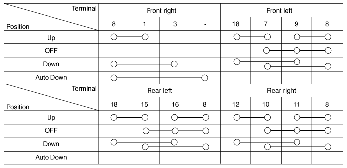
[Front Auto Down]
(LHD)
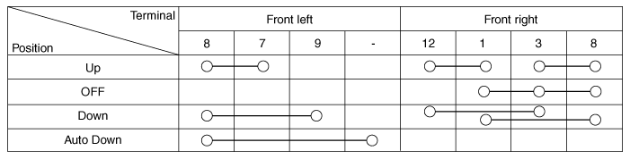
(Right-Hand Drive)
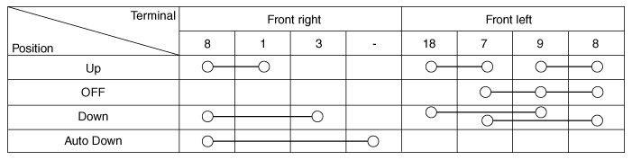
Auxiliary / Rear Power Window Switch
Disconnect the negative (-) battery terminal.
Remove the front right door trim panel.
(Refer to Body - "Front Door Trim Panel")
(Refer to Body - "Rear Door Trim Panel")
Disconnect the power window switch connector from the door trim panel.
[Auxiliary Power Window Switch]
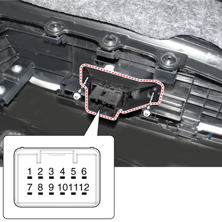
[Rear Power Window Switch]
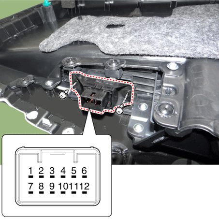
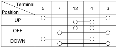
Check the continuity between the terminals at each switch position according to the table. If the continuity is not as specified, replace the switch.
Diagnosis Using KDS/GDS
The body electrical system can be quickly diagnosed for faulty parts using the vehicle diagnostic system (KDS/GDS).
The diagnostic system (KDS/GDS) provides the following information.
Self-Diagnosis: Checks and displays diagnostic trouble codes (DTC)
Current Data: Checks the input/output status of the system.
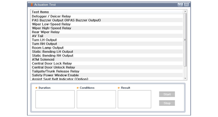
Actuation Test: Checks the operating condition of the system.
Additional Functions: Other controls such as system option and zero point
Select the "Vehicle Model" and the system to be checked in order to inspect the vehicle with the scan tool.
Select "Body Control Module (BCM)" to check the body control module (BCM).
Select the "Current Data" menu to view the current input/output data status.
The input/output data for the sensors related to the door lock switch can be checked.
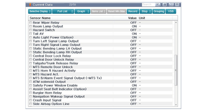
To forcibly check the operation of the power door lock, select the "Active Test" of the BCM.
Test yourself
A quick Kia Rio YB quiz: every answer comes with an explanation and a link to the manual page.