Work on the dashboard
FLOOR CONSOLE
REMOVAL AND REFITTING
- Unclip the gaiter (1) of the gear lever and fold it back over the gear knob (Fig.11).
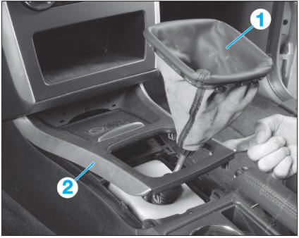
Fig. 11
- Unclip the cover (2) and remove it by pulling it towards the rear.
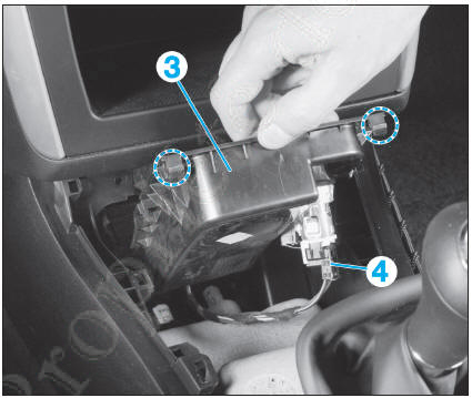
Fig. 12
- Remove the screws (5) and (6) securing the floor console (Fig.13) and (Fig.14).
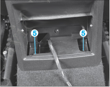
Fig. 13
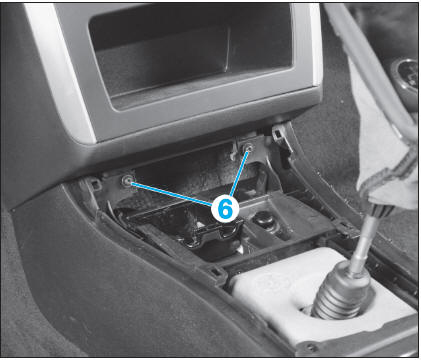
Fig. 14
- Pull the parking brake lever fully up.
- Lift the rear of the floor console slightly and disconnect the connectors (depending on version).
- Release the floor console by sliding it off the parking brake lever.
 To make the operation easier, it is advisable to remove the handle of the parking brake lever. To do this, unlock the retaining clip on the underside of the handle by pushing it downwards. This clip is accessible through the seam of the leather trim.
To refit, carry out the removal procedure in reverse order.
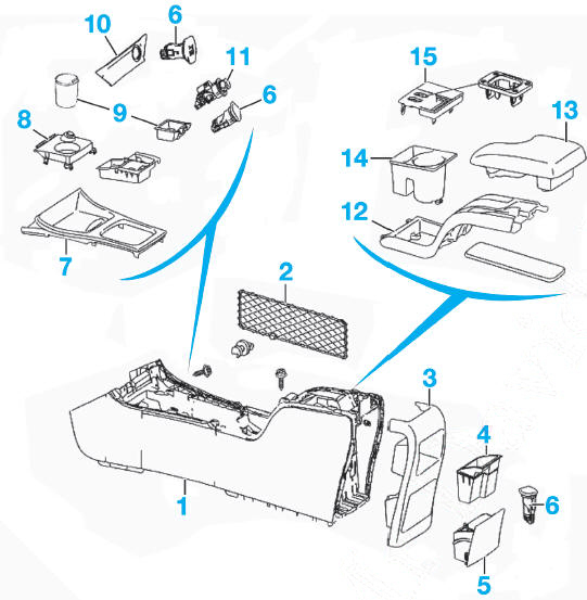
Floor console
- Floor console
- Net pocket
- Rear trim
- 12 V socket
- Gear selector trim
- Holder
- Trim
- Armrest trim
- Armrest lid
- Cup holder
- Switch trim.
GLOVE BOX
REMOVAL AND REFITTING
- Remove the screws (1) (Fig.15).
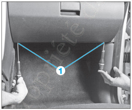
Fig. 15
- Release the door surround seal from the dashboard.
- If fitted, remove the CD changer from the glove box.
- Remove the side cover (2), then the screw (3) (Fig.16).
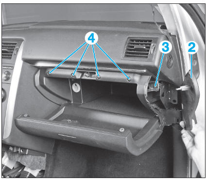
Fig. 16
- Remove the covers and the screws (4).
- Move the glove box slightly towards the rear and disconnect the connectors (5) and (6), as well as the refrigerant pipe (7) (Fig.17).
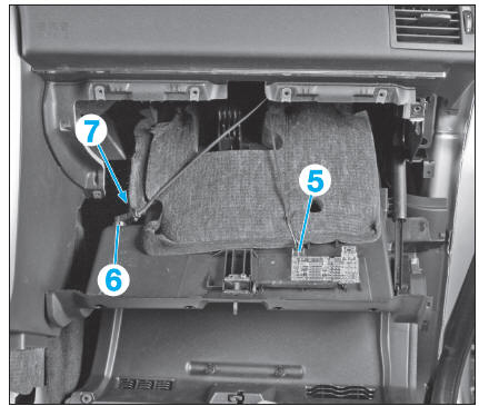
Fig. 17
- Remove the glove box.
To refit, carry out the removal procedure in reverse order.
INSTRUMENT CLUSTER
REQUIRED TOOLS
- [1]. Extraction tool (ref. 140 589 02 33 00) (Fig.18).
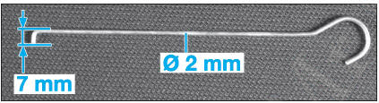
Fig. 18
REMOVAL AND REFITTING
- Insert the tools [1] approximately 40 mm (Fig.19).
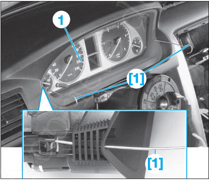
Fig. 19
- Turn the hooks 90° inwards to operate the locks.
- Pull the instrument cluster (1) towards the rear.
- Disconnect the connector.
- Remove the instrument cluster (1).
When refitting, the instrument cluster must click audibly into place.
DASHBOARD
REQUIRED TOOLS
- [1]. Extraction tool (ref. 140 589 02 33 00) (Fig.24).
REMOVAL AND REFITTING
- Remove (see relevant operation):
- the floor console,
- the glove box,
- the instrument cluster.
Removal of trim panels under the dashboard
- Driver's side (Fig.20):
- if fitted, unclip the footwell light and push it through the trim panel,
- remove the screw (1), then release the bonnet release lever,
- remove the screws (2), then lower the trim panel,
- separate the diagnostic connector from its holder.
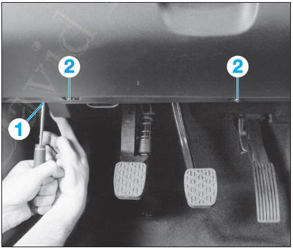
Fig. 20
- Passenger's side (Fig.21):
- if fitted, unclip the footwell light and push it through the trim panel,
- remove the screws (3), then lower the trim panel.
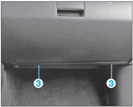
Fig. 21
Removal of centre console components
- Unclip the cover (4) of the centre console at the arrows, starting from the bottom (Fig.22).
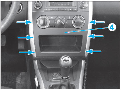
Fig. 22
- Depending on equipment (Parktronic system, heated seats, etc.), disconnect the connectors.
- On vehicles fitted with automatic air conditioning, close the upper air outlet using the adjusting wheel (5) (Fig.23).
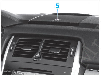
Fig. 23
- Using hooks [1], unlock the two fixings of the centre vent (6) and extract it towards the rear (Fig.24).
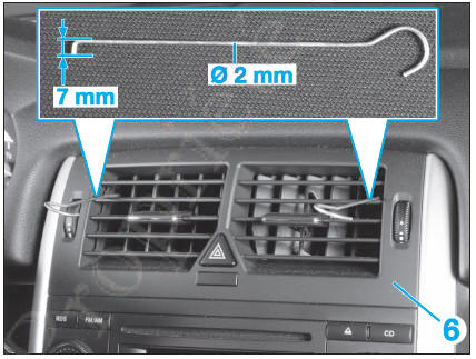
Fig. 24
- Disconnect the connector of the hazard warning switch.
- Remove the screws (7), operate the locks (8) and extract the radio (9) towards the rear (Fig.25).
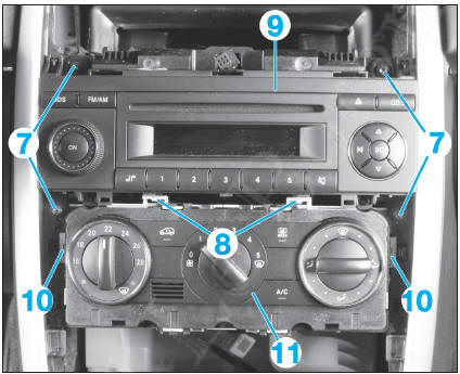
Fig. 25
- Disconnect the radio connectors.
- On vehicles fitted with semi-automatic air conditioning, set the rotary air distribution knob to the 'general ventilation' position. The levers are thereby placed in a position that makes it easier to disconnect the cables.
- Operate the locks (10) and release the air conditioning control panel (11) towards the front, rotate it, then extract it from below.
- On vehicles fitted with semi-automatic air conditioning, release the retaining clips (12) and disconnect the cables from the ball joints (13) (Fig.26).
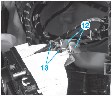
Fig. 26
- Disconnect the connectors from the air conditioning control panel.
- Remove the driver's airbag (see chapter 'AIRBAGS AND PRETENSIONERS').
- Remove the steering wheel (see chapter 'STEERING').
- Unscrew the screw located on the right-hand side of the combination switch / clockspring assembly (14). Pull the assembly straight out along the axis of the steering column (Fig.27).
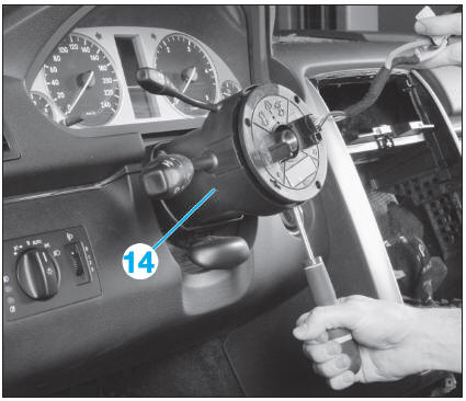
Fig. 27
- Remove the light switch. To do so (Fig.28):
- detach the cover (15),
- detach the headlight levelling knob (16) and pass it with its wiring through the hole in the dashboard,
- slide the light switch (17) to the right and push it forward,
- remove the light switch from underneath and disconnect it.
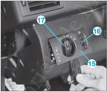
Fig. 28
- Unscrew the ring (18) and push the ignition switch (19) forward (Fig.29).
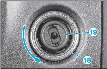
Fig. 29
- Disconnect the steering column height adjustment control.
To do so, push the locking lever (20) forward and drive it downwards with a screwdriver (21) of suitable size (Fig.30).
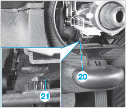
Fig. 30
Remove the windscreen pillar trims (22). To do so, push the trim upwards as far as it will go, then pull the top of the trim inwards to unclip it. If fitted, disconnect the tweeter connector (Fig.31).
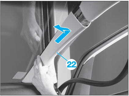
Fig. 31
- Remove the upper dashboard grille (23) (Fig.32).
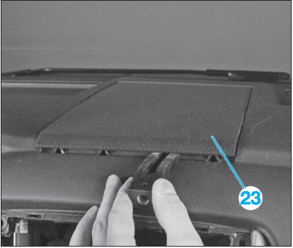
Fig. 32
- Depending on equipment (automatic air conditioning, etc.), disconnect the connectors and remove the speaker.
- Remove the passenger airbag (see chapter 'AIRBAGS AND PRETENSIONERS').
- Remove the screw (24) on the left-hand side (Fig.33).
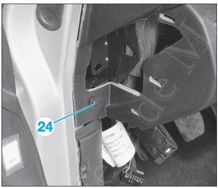
Fig. 33
- Remove the screws (25) on each side of the dashboard (Fig.34).
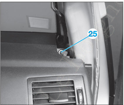
Fig. 34
- Push the dashboard forward at the centre air vent, then lift it to release it from the retainer (26) (Fig.35).
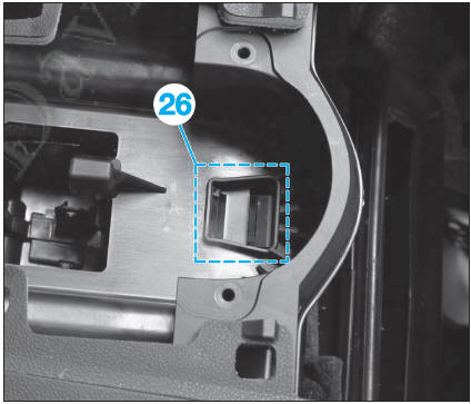
Fig. 35
- Pull the dashboard rearwards, taking care that no cables remain connected.
To refit, reverse the removal procedure, observing the following points:
- take care when routing the wiring harnesses,
- make sure all connectors are correctly connected,
- after reconnecting the battery, make sure all dashboard equipment works correctly.
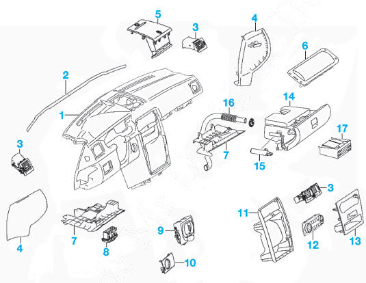
Dashboard
- Dashboard
- Seal
- Air vents
- Side covers
- Upper grille
- Side airbag
- Under-dashboard trim
- Diagnostic connector bracket
- Steering column adjustment trim
- Lighting controls trim
- Centre console trim
- Climate control unit
- Climate control trim
- Glove box
- Actuator
- Glovebox cooling duct
- CD changer.
DASHBOARD CROSSMEMBER
REMOVAL AND REFITTING
- Remove the dashboard (see relevant operation).
- Disconnect the remaining connectors still connected, then remove the crossmember wiring harness.
- Remove (Fig.36):
- the screw (1),
- the screws (2) and lower the steering column to the floor,
- the bolt (3),
- the screws (4).
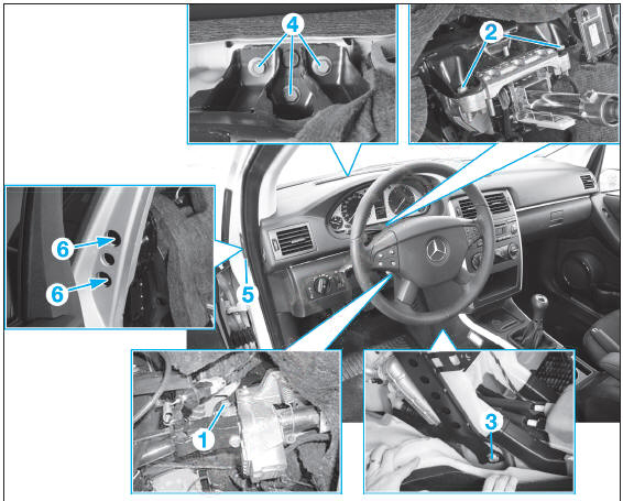
Dashboard crossmember mountings Fig. 36
- On each side, remove:
- the cover (5),
- the screws (6).
- Pull the crossmember out slightly until you can access the cable clamps on the wiring harnesses at the ends of the dashboard, then remove them.
- Pull the dashboard crossmember completely out.
To refit, reverse the removal procedure, tightening the steering column screws (1) and (2) to 2 daN.m and the crossmember screws (3), (4) and (6) to 2.3 daN.m.
Test yourself
A quick Mercedes-Benz B-Class quiz: every answer comes with an explanation and a link to the manual page.