Body inspection
General information
Three types of check can be carried out before putting the vehicle on the straightening bench:
* the check of gaps and flush measurements, which can help determine the extent and location of deformation. This check also serves as a reference when removing/refitting or replacing removable parts.
* Gauge check referring to the underbody plan, structural dimensions or by symmetry.
* Checking the front suspension is also an excellent way to verify whether the underbody has been affected. However, do not overlook the running gear components, which may also have been deformed and could distort the diagnosis.
Gauge check
 v
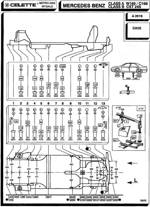
 Dimensions are for reference only. Measurements taken with the straightening gauge set are decisive
FRONT SECTION
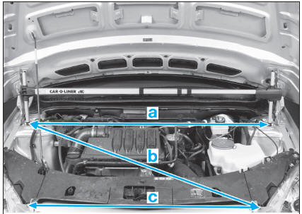
a = 1264 mm
b = 1281 mm
c = 935 mm.
REAR SECTION
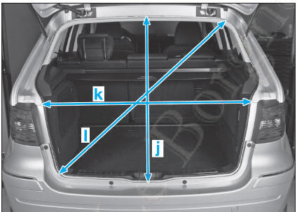
j = 923 mm
k = 1157 mm
l = 1285 mm.
SIDE SECTION
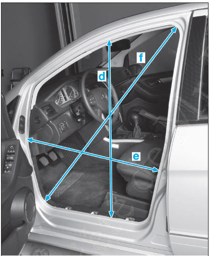
d = 1004 mm
e = 842 mm
f = 1346 mm.
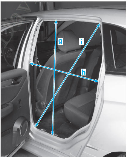
g = 1065 mm
h = 775 mm
i = 1223 mm.
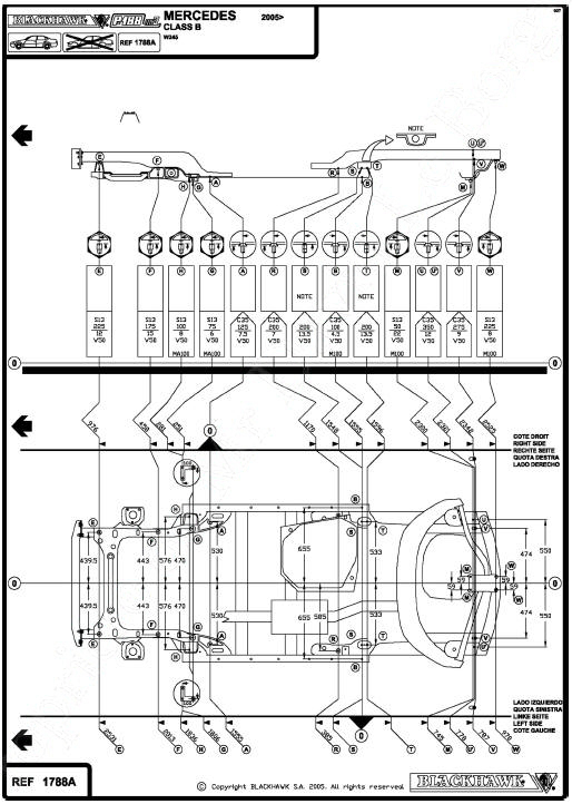
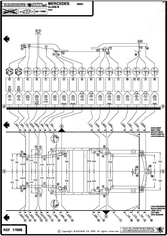
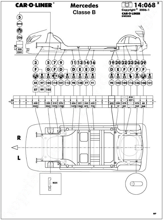
Blackhawk
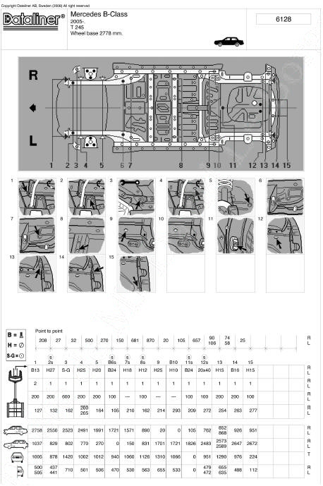
Dataliner
- Bumper mounting, lower outer bolt toward front
- Side rail, front bolt (washer)
- Front fender, 8 mm hole
- Front side member, 1st hole toward outside
- Front side member, hole toward outside
- Side rail, rear bolt (washer)
- Front side member, last hole
- Crossmember, small outer hole
- Rocker panel, rear hole
- Rear side member reinforcement, center hole
- Rear side rail, front center bolt
- Rear side member, oval hole
- Rear side member, rear hole
- Bumper mounting, lower bolt toward rear
- Rear crossmember, outer hole
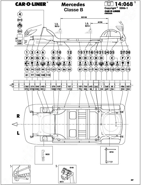
Car-o-liner
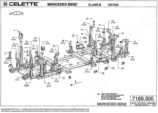
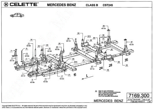
FUNCTION OF COMPONENTS
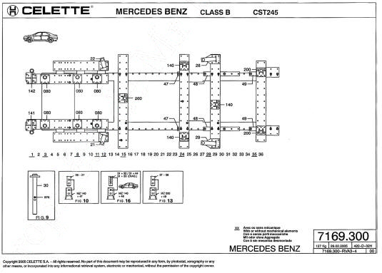
MZ141-MZ142 1-2-3-4: Check of front energy-absorbing crossmember mounting.
MZ260 5-6: Check of front subframe front mounting, engine removed.
7: Locating pins for front subframe front mounting, engine removed.
MZ080 5-6: Check of front subframe front mounting, engine not removed.
8: Locating pins for front subframe front mounting, engine not removed.
MZ601-MZ602 9-10: Check of front shock absorber mounting.
11: Pins for checking front shock absorbers.
MZ260 12-13: Guide and check of front subframe center mounting, engine removed.
14: Guide pins for front subframe center.
15: Locating pins for front subframe center and rear mounting, engine removed.
MZ080 12-13: Check of front subframe center mounting, engine not removed.
16: Front subframe centre mounting locators, powertrain not removed.
MZ200 17-18: Front subframe rear mounting check, powertrain removed.
MZ080 17-18: Front subframe rear mounting check, powertrain not removed.
20: Front subframe rear mounting locators, powertrain not removed.
21-22: Brackets for front lateral locating.
23: Locators for front lateral locating.
MZ260 24: Centre reference locating.
25: Pin for centre reference locating.
MZ140 26: Front right locating of the rear side member.
MZ14D 27: Front left locating of the rear side member.
28-29: Brackets for rear lateral locating.
30: Locators for rear lateral locating.
MZ260 31: Front centre mounting check of the rear axle, powertrain removed.
MZ140 31: Front centre mounting check of the rear axle, with powertrain.
32: Front centre mounting locator of the rear axle, with powertrain (mounting).
33: Front centre mounting locator of the rear axle, with powertrain (diagnostic).
19: Front centre mounting locator of the rear axle, powertrain removed.
MZ6D1-MZ602 34-35: Rear shock absorber mounting check.
36: Locators for front shock absorber check.
MZ200 37-38: Rear side member rear locating check.
MZ080 39: Rear axle lower rear centre mounting check, without powertrain.
40: Rear axle upper rear centre mounting check, powertrain removed.
MZ260 41-42: Rear skirt check.
43: Shim that compensates the closing panel when removed.
44: Locator for the front centre mounting of the rear axle, with powertrain (use when the original thread has been damaged and replaced by the MERCEDES original adapter).
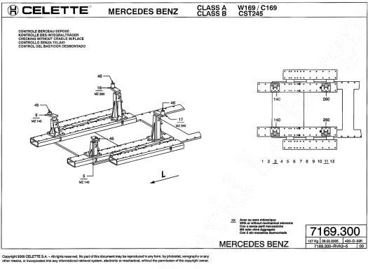
45: Locators for subframe check on the measuring table (front mounting).
46: Locators for subframe check on the measuring table (rear mounting).
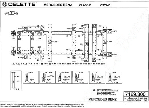
47: Displacement shim for modular crossmember (checked model CST 245).
48: Displacement shim for modular crossmember (checked model CST 245).
49: Displacement shim for modular crossmember (checked model CST 245).
50-51: Storage cases for fasteners.
52: Screw for front centre mounting check of the rear axle, powertrain removed.
USE OF PARTS
 When ordering spare parts, refer to assembly plan 420- D-32A to specify the 8-digit part number '7169.7'-'.
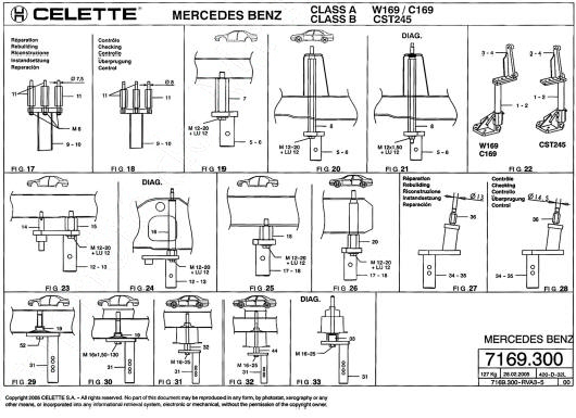
Front shock absorber bracket check and installation
When replacing the front shock absorber bracket, use the large diameter (8 mm) of pin 11 and secure the bracket to parts 9-10 using HM8 nuts.
When checking, use the small diameter (7.5 mm) of pin 11.
Front subframe front mounting check
Powertrain removed:
Screw locator 7 onto the side member, lock parts 5-6 in the MZ260 towers as shown, lower the vehicle and secure locators 7 to parts 5-6 using the supplied HM 12-20 screws and LU12 washers.
Powertrain not removed (mounting):
Remove the vehicle screws and fit locators 8 under the subframe as shown.
Lock parts 5-6 in the MZ080 towers.
 This operation must be performed one side after the other.
Lower the vehicle and secure locators 8 to parts 5-6 using the supplied HM 12-20 screws and LU12 washers.
Powertrain not removed (diagnostic):
On the measuring table, install the MZ080 towers fitted with parts 5-6.
Secure locators 8 to parts 5-6 using HM12X1.50 nuts and the supplied LU 12 washers.
Lower the vehicle, which will centre on locators 8 through the subframe mounting screw heads.
Front absorber crossmember mounting check
Depending on the checked vehicle model W169/C169 or CST245, see the position and rotation of parts 1-2-3-4.
Front subframe centre mounting check
Powertrain removed:
Fix locator 15 to the side member.
On the measuring table, install the MZ260 towers fitted with parts 12/13 and centring pin 14.
Lower the vehicle, which will centre on parts 12/13 through locators 15 and pins 14.
Secure locators 15 to parts 12/13 using the supplied HM12-20 screws and LU12 washers.
Powertrain not removed (DIAG).
On the measuring table, install the MZ080 towers fitted with parts 12/13.
Secure locators 16 to parts 12/13 using the supplied HM12-20 screws and LU12 washers.
Lower the vehicle, which will centre on locators 16 through the subframe mounting screw heads.
Front subframe rear mounting check, powertrain removed: Fix locators 15 to the side member.
On the measuring table, install the MZ200 towers fitted with parts 17/18.
Lower the vehicle, which will centre on parts 17/18 through locators 15.
Secure locators 15 to parts 17/18 using the supplied HM12-20 screws and LU 12 washers.
Powertrain not removed (mounting): On the vehicle, remove the subframe rear mounting screws and screw locators 20 onto the vehicle.
When ordering spare parts, refer to assembly plan 420- D-32A to specify the 8-digit part number '7169.7'-'.
Front shock absorber bracket check and installation. When replacing the front shock absorber bracket, use the large diameter (8 mm) of pin 11 and secure the bracket to parts 9-10 using HM8 nuts.
When checking, use the small diameter (7.5 mm) of pin 11.
Front subframe front mounting check
Powertrain removed:
Screw locator 7 onto the side member, lock parts 5-6 in the MZ260 towers as shown, lower the vehicle and secure locators 7 to parts 5-6 using the supplied HM 12-20 screws and LU12 washers.
Powertrain not removed (mounting):
Remove the vehicle screws and fit locators 8 under the subframe as shown.
Lock parts 5-6 in the MZ080 towers.
This operation must be performed one side after the other.
This operation must be performed one side after the other.On the measuring table, install the MZ080 towers fitted with parts 17/18.
Lower the vehicle, which will centre on parts 17/18 through locators 20. Secure locators 20 to parts 17/18 using the supplied HM12-20 screws and LU12 washers.
Rear shock absorber bracket check and installation
Powertrain removed:
When replacing the rear shock absorber bracket, use the large diameter (14.5 mm) of locator 36 on parts 34/35.
When checking, use the small diameter (13 mm) of locator 36.
Front centre mounting check of the rear axle.
Powertrain removed:
On the measuring table, install the MZ260 tower fitted with part 31 and locator 19.
Lower the vehicle, which will centre on locator 19.
Secure the vehicle with screw 52 or screw HM16x1.50-130, depending on the configuration of the checked vehicle.
Powertrain not removed (mounting):
Remove the vehicle bolt and screw in centring pin 32 or 44, depending on the configuration of the vehicle being checked.
On the alignment plate, fit tower MZ140 equipped with part 31.
Lower the vehicle so that it centres on part 31 via centring pin 32 or 44.
Fix centring pin 32 or 44 to part 31 with the supplied HM16-25 bolt.
Without removing the engine and drivetrain (DIAG):
On the alignment plate, fit tower MZ140 equipped with part 31 and centring pin 33.
Lower the vehicle so that it centres on centring pin 33 via the rear axle mounting bolt head.
 All vehicle bolts that have been removed must be replaced with new bolts.
Celette metro 2000 mygale
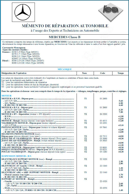
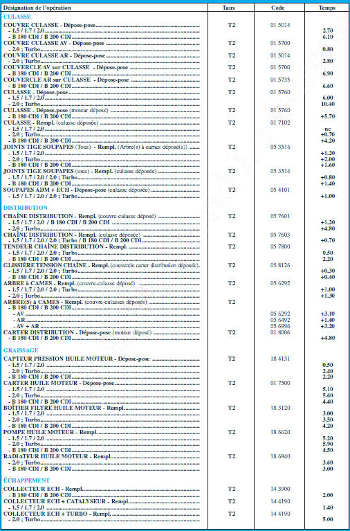
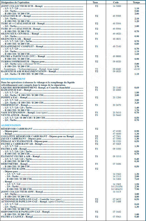
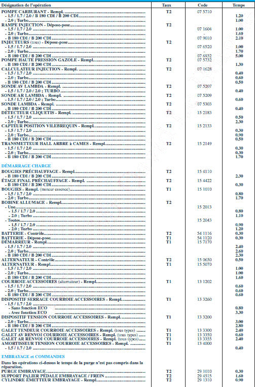
MERCEDES Class B
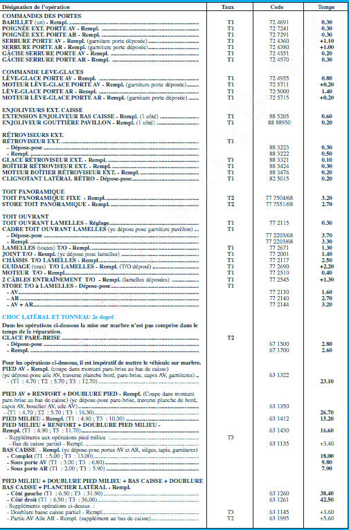
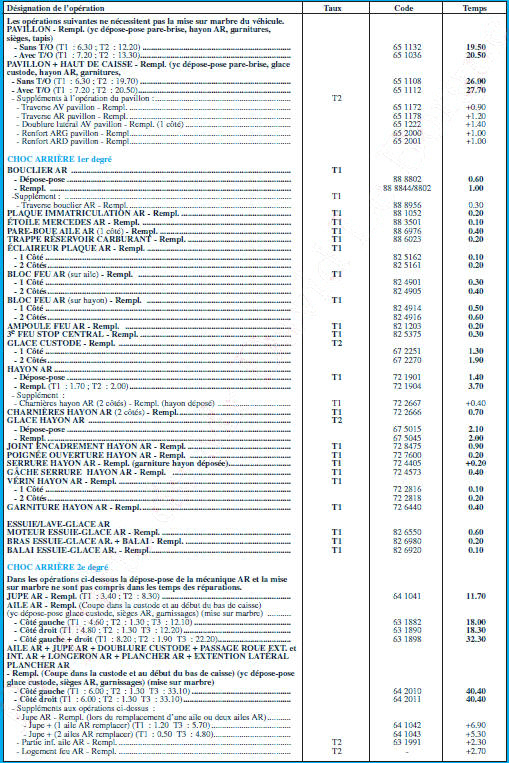
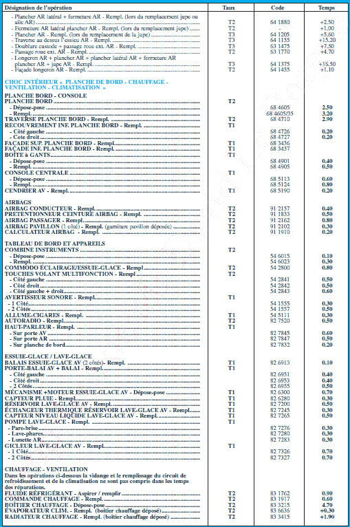
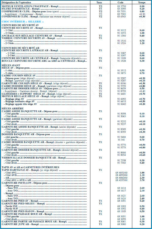
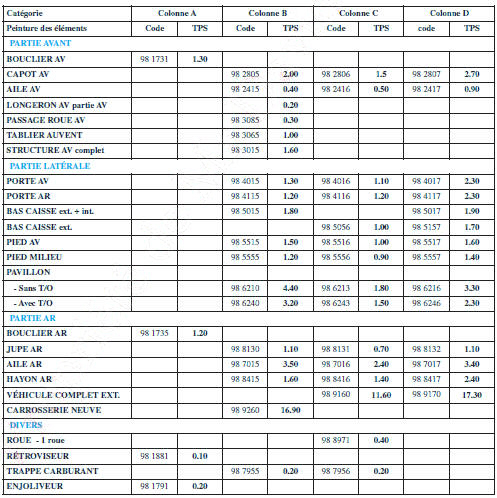
INSTRUCTIONS FOR USING PAINT TIMES
There are 4 paint categories (two-coat paint):
- Column A: Paint, no level (applies to small removed body parts in metal or plastic)
- Column B: Paint level 1 (applies to a new replacement part, bolt-on or welded)
- Column C: Paint level 2 (applies to a straightened part)
- Column D: Paint level 3 (applies to a repaired part)
METHOD FOR CALCULATING PAINT TIMES FOR ADJACENT BODY PANELS
Proceed as follows:
- Billing for 2 adjacent panels: 15% discount.
- Billing for 3 adjacent panels: 20% discount.
- Billing for 4 or more adjacent panels: 25% discount.
PREPARATION TIME
There are therefore several PREPARATION TIME categories.
Each preparation time category takes into account the position of the part to be painted (on vehicle or removed).
The preparation time applied is that corresponding to the most complete job; for the other parts, an additional allowance is added regardless of the number of parts to be painted.
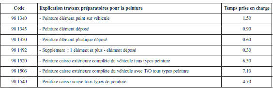
MATERIALS - The price of materials per hour of labour must be calculated by each repairer based on the products used, their own purchasing conditions and their own consumption. It depends on the paints used.
Billing is obtained by multiplying the price per hour of materials by the total paint labour time.
Anti-chip products must be billed separately from materials, according to the application carried out.
PAINT ESTIMATE EXAMPLE
Case of a side impact with rear adjacent and non-adjacent panels on vehicle.
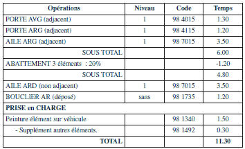
INDICATIVE BILLING TIMES
Expressed in hours and hundredths of an hour 14
Test yourself
A quick Mercedes-Benz B-Class quiz: every answer comes with an explanation and a link to the manual page.