Diagnosis - Interpreting XR25 bar graphs
KANGOO ALL TYPES

INSTRUCTIONS None
Replace the air conditioning control unit

INSTRUCTIONS None
| Before establishing communication between the XR25 tool and the control unit, check that the ignition is on. |
| Make sure the XR25 tool is not the cause of the fault by trying to communicate with a control unit on another vehicle. Check that the ISO interface is in position S8, that you are using the latest XR25 cassette and the correct access code (D 17). Check the battery voltage (U > 10.5 volts). Recharge the battery if necessary. |
| Check that the control unit connectors are fully clipped in. Check that the air conditioning control unit is correctly supplied:
|
| Check that the diagnostic socket is correctly supplied:
L line, pin 3 of the air conditioning control unit |
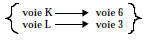 of the 30-way blue connector on the unit
AFTER REPAIR You can start diagnosis.

INSTRUCTIONS None
Low level
| Check that the refrigerant sensor connector is correctly clipped in. Clip the connector in correctly if necessary. |
| Check continuity and insulation to earth of the wiring between pins A, B and C of the sensor and pins 9, 10 and 11 of the 30-way connector of the air conditioning control unit. (sensor supplied with 5 V). Repair the faulty wiring. |
| Connect the XR25 tool and perform a # 16. Measure the refrigerant pressure. The low pressure must be less than or equal to 2 bar. Is it correct? |
YES Replace the refrigerant pressure sensor.
NO Recharge the refrigerant.
AFTER REPAIR Enter G0** on the XR25 tool.
Check that the system operates correctly.

High level
| Check that the refrigerant sensor connector is correctly clipped in. Clip the connector in correctly if necessary. |
| Check the condition of the wiring between pins A, B and C of the sensor and pins 9, 10 and 11 of the 30-way connector of the air conditioning control unit (sensor supplied with 5 V). Repair the faulty wiring. |
| Connect the XR25 tool and run # 16. Measure the refrigerant pressure. The high pressure must be less than or equal to 28 bar. Is it correct? |
YES Replace the refrigerant pressure sensor.
NO Recharge the refrigerant.
AFTER REPAIR Enter G0** on the XR25 tool.
Check that the system operates correctly.

NOTE Before any disassembly, enter G0** on the XR25 tool and restart the system.
Use the XR25 tool to enter G21* and activate the compressor.
Does the compressor engage?
| YES | Using the XR25 tool, check the circuit pressure (# 16). At an ambient temperature of about 20 °C, the pressure must be between 2 and 28 bar. Is the pressure between these values? |
| YES Replace the clutch. | |
| NO Recharge the refrigerant circuit. Repair the circuit if necessary. If the left-hand bargraph 4 stays on steadily, replace the clutch. If the left-hand bargraph 4 still stays on steadily, replace the compressor. |
NO See the diagnosis for left-hand bargraph 4 on, CONTINUED 1.
AFTER REPAIR Enter G0** on the XR25 tool.
Check that the system operates correctly.

Check for 12 volts on pin 1 of the clutch connector.
Is there 12 volts?
| YES | Check the condition of the compressor earth. Is the compressor earth in good condition? |
| YES Check the continuity and absence of short circuits in the wiring between the clutch and the compressor. If the wiring is faulty, repair it. If the wiring is in good condition, replace the compressor. |
|
| NO Repair the compressor earth. |
| NO | Check the continuity and absence of short circuits in the wiring between clutch pin 1 and pins 2 and 17 of the 30-pin air conditioning control unit connector. Repair the wiring if necessary. |
| For petrol vehicles: use the XR25 sheet corresponding to the vehicle. With the engine running, operate the A/C, then check on the XR25 sheet whether the bargraph "Compression allowed or not allowed" is lit. Is the bargraph lit? |
|
| YES Check and repair the wiring. NO See the diagnosis for bargraph 4 G on, CONTINUED 2. |
AFTER REPAIR Enter G0** on the XR25 tool.
Check that the system operates correctly.

For petrol vehicles: use the injection XR25 sheet corresponding to the vehicle.
With the engine running, operate the A/C, then check on the XR25 sheet whether the bargraph "A/C authorisation" is lit.
Is the bargraph lit?
YES There is a fault on the injection side.
Refer to the injection diagnosis for the vehicle.
| NO | Check the continuity and absence of short circuits in the wiring. Repair if necessary. Check for 12 volts on pins 2 and 17 of the 30-pin air conditioning control unit connector. Is there 12 volts? |
| YES There is a fault on the injection side. Refer to the injection diagnosis for the vehicle. |
|
| NO Check that the evaporator temperature sensor is correctly installed. Check its resistance: disconnect the evaporator temperature sensor and measure the resistance across its terminals. The resistance must be between 90 ohms and 13.7 kohms. If the evaporator temperature sensor is in good condition, replace the air conditioning control unit. If the evaporator temperature sensor is in poor condition, replace it. |
AFTER REPAIR Enter G0** on the XR25 tool.
Check that the system operates correctly.

NOTE This fault only appears on the XR25 tool if air recirculation is requested.
| Check the condition of the air recirculation flap control motor. At the motor connector, measure the resistance between the two pins. Replace the recirculation motor if necessary. |
| Check the condition of the wiring between the pins: control panel Repair if necessary. |
| Check the continuity and insulation from earth and from 12 volts of the wiring between the pins: air recirculation motor connector Repair the faulty wiring. |
| If the fault persists, replace the air conditioning control unit. |
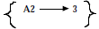 red 15-pin connector of the air conditioning control unit
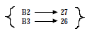 blue 30-pin connector of the air conditioning control unit
AFTER REPAIR Enter G0** on the XR25 tool.
Check that the system operates correctly.

NOTE Check that air conditioning has been requested.
Check that bargraph 6D is off; if not, diagnose 6D first.
Enter G0** on the XR25 tool.
If bargraph 6G stays on, you can start the diagnosis.
| Check the earth of the GMV (2) (the relay is controlled by a 0 volt signal). Repair the GMV earth if necessary. |
| Connect the XR25 tool and run #16. Check that the refrigerant pressure is approximately 20 bar. If this is not the case, recharge the refrigerant (control of the cooling GMV depends on the refrigerant pressure). |
| Check the wiring between the GMV (2) relay and pin 10 of the injection ECU. Repair it if necessary. |
| Check the operation of the relay by entering G23* on the XR25 tool. The GMV should be heard clicking. Is the GMV heard clicking? |
YES Check the continuity and insulation from 12 volts of the wiring between pin F2 and pin 23 of the 30-pin air conditioning control unit connector.
Repair the faulty wiring.
NO Replace the GMV (2) relay.
AFTER REPAIR Enter G0** on the XR25 tool.
Check that the system operates correctly.

NOTE Check that air conditioning has been requested.
Enter G0** on the XR25 tool.
If bargraph 6D stays on, you can start the diagnosis.
| Check that air conditioning is switched on. GMV (1) is activated as soon as the air conditioning is switched on. |
| Check the earth of GMV (1) (the relay is controlled by a 0 volt signal). Repair the GMV earth if necessary. |
| Connect the XR25 tool and run #16. Check that the refrigerant pressure is approximately 10 bar. If this is not the case, recharge the refrigerant (control of the cooling GMV depends on the refrigerant pressure). |
| Check the operation of the relay by entering G22* on the XR25 tool. The GMV should be heard clicking. Is the GMV heard clicking? |
YES Check the continuity and insulation from 12 volts of the wiring between pin M2 and pin 22 of the 30-pin air conditioning control unit connector.
Repair the faulty wiring.
NO Replace the GMV (1) relay.
AFTER REPAIR Enter G0** on the XR25 tool.
Check that the system operates correctly.

NOTE This bargraph lights outside the start-up phase.
If it is not lit, the compressor and the GMVs will not be activated.
| Check the condition of the +SERV fuse. Repair it if necessary. |
| Check the condition of the wiring between terminal A26 of the fuse box and terminal B1 of the air conditioning control panel. Repair the faulty wiring if necessary. |
AFTER REPAIR Check that the system operates correctly.

NOTES This bar graph must be off when the engine is running.
If it is on, you can carry out the diagnosis.
| First check that air conditioning has been requested (request on the control panel). |
| Check the continuity of the wiring between pin 5 of the injection ECU and pin 13 of the 30-pin connector of the A/C control module (P.A. information). Repair it if necessary. |
Check the continuity of the wiring between:
Repair it if necessary. |
| If the problem persists, check the injection diagnosis, as this is an injection-related fault. |
AFTER REPAIR Check that the system operates correctly.
Test yourself
A quick Renault Kangoo quiz: every answer comes with an explanation and a link to the manual page.