ECU Terminals
ECU TERMINALS
CHECK INSTRUMENT PANEL JUNCTION BLOCK ASSEMBLY AND MAIN BODY ECU (MULTIPLEX NETWORK BODY ECU)
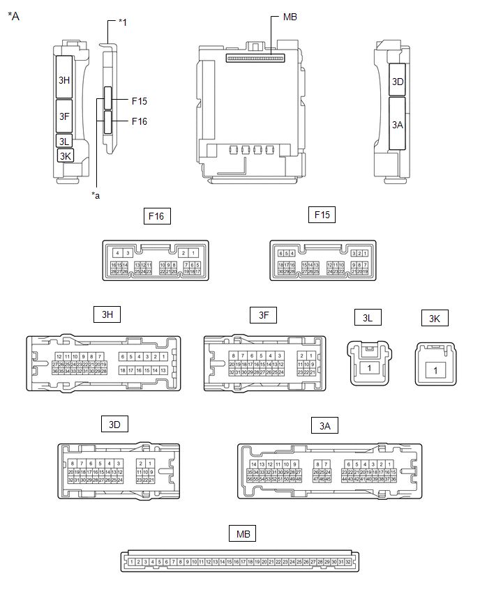
*A |
Main Body ECU (Multiplex Network Body ECU) with 2 connectors |
- |
- |
*1 |
Main body ECU (multiplex network body ECU) |
- |
- |
*a |
2 connectors |
- |
- |
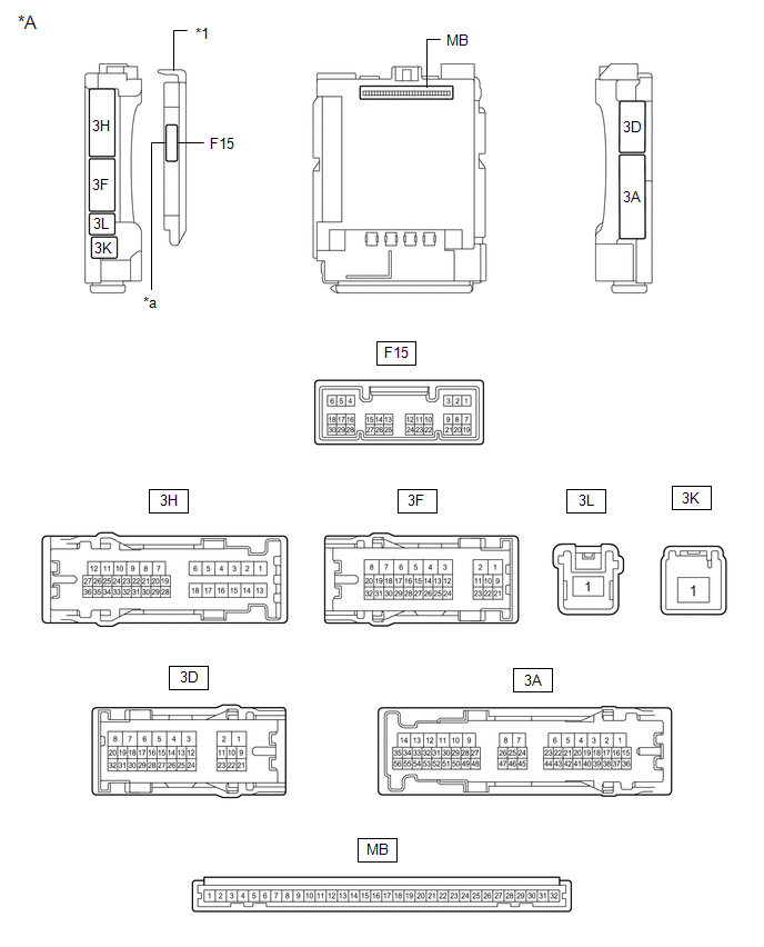
*A |
Main Body ECU (Multiplex Network Body ECU) with 1 connector |
- |
- |
*1 |
Main body ECU (multiplex network body ECU) |
- |
- |
*a |
1 connector |
- |
- |
(a) Remove the main body ECU (multiplex network body ECU) from the instrument panel junction block assy.
Click here
(b) Reconnect the connectors to the instrument panel junction block assy.
(c) Measure the voltage and resistance according to the value(s) in the table below.
Terminal No. (Symbol) | Wire Color | Terminal Description | Condition | Specified Condition |
|---|---|---|---|---|
MB-11 (GND1) - Body ground |
- |
Ground |
Always |
Below 1 Ω |
MB-30 (ACC) - Body ground |
- |
ACC power supply |
Ignition Switch in ACC position |
11 à 14 V |
MB-30 (ACC) - Body ground |
- |
ACC power supply |
Ignition Switch in OFF position |
Below 1 V |
MB-31 (BECU) - Body ground |
- |
Battery power supply |
Always |
11 à 14 V |
MB-32 (IG) - Body ground |
- |
IG power supply |
Ignition Switch in ON position |
11 à 14 V |
MB-32 (IG) - Body ground |
- |
IG power supply |
Ignition Switch in OFF position |
Below 1 V |
(d) Reinstall the main body ECU (multiplex network body ECU) onto the instrument panel junction block assy.
Click here
(e) Measure the voltage and check the pulses according to the value(s) in the table below.
Terminal No. (Symbol) | Wire Color | Terminal Description | Condition | Specified Condition |
|---|---|---|---|---|
F15-2 (UL3) - Body ground |
L - Body ground |
Key-linked driver side door unlock input |
Driver's door lock cylinder from neutral position → ON (unlock) |
Pulse generation → Below 1 V |
F15-29 (L2) - Body ground |
G - Body ground |
Key-linked driver side door lock input |
Driver's door lock cylinder from neutral position → ON (lock) |
Pulse generation → Below 1 V |
F15-6 (FLCY) - Body ground |
R - Body ground |
Front door (left) courtesy light switch input voltage |
Front left door open |
Below 1 V |
F15-6 (FLCY) - Body ground |
R - Body ground |
Front door (left) courtesy light switch input voltage |
Front left door closed |
Pulse generation |
F15-27 (FRCY) - Body ground |
BR - Body ground |
Front door (right) courtesy light switch input voltage |
Front right door open |
Below 1 V |
F15-27 (FRCY) - Body ground |
BR - Body ground |
Front door (right) courtesy light switch input voltage |
Front right door closed |
Pulse generation |
3H-8 (ACT-) - Body ground |
LA-B - Body ground |
Door lock motor UNLOCK control output |
Door control switch or driver's door key cylinder OFF → ON (unlock) |
Below 1 V → 11 to 14 V → Below 1 V |
3H-9 (ACT-) - Body ground |
B - Body ground |
Door lock motor UNLOCK control output |
Door control switch or driver's door key cylinder OFF → ON (unlock) |
Below 1 V → 11 to 14 V → Below 1 V |
3H-6 (ACT+) - Body ground |
R - Body ground |
Door lock motor LOCK control output |
Door control switch or driver's door key cylinder OFF → ON (lock) |
Below 1 V → 11 to 14 V → Below 1 V |
3H-18 (ACT+) - Body ground |
R - Body ground |
Door lock motor LOCK control output |
Door control switch or driver's door key cylinder OFF → ON (lock) |
Below 1 V → 11 to 14 V → Below 1 V |
3D-4 (ACTD) - Body ground |
B - Body ground |
Door lock motor UNLOCK control output |
Door control switch or driver's door key cylinder OFF → ON (unlock) |
Below 1 V → 11 to 14 V → Below 1 V |
3H-24 (LCTY) - Body ground |
BR - Body ground |
Rear door courtesy light switch input voltage (left) |
Rear LH door open |
Below 1 V |
3H-24 (LCTY) - Body ground |
BR - Body ground |
Rear door courtesy light switch input voltage (left) |
Rear LH door closed |
Pulse generation |
3A-31 (RCTY) - Body ground |
BR - Body ground |
Rear door courtesy light switch input voltage (right) |
Rear RH door open |
Below 1 V |
3A-31 (RCTY) - Body ground |
BR - Body ground |
Rear door courtesy light switch input voltage (right) |
Rear RH door closed |
Pulse generation |
3H-34 (BCTY) - Body ground |
SB - Body ground |
Luggage compartment door courtesy light switch input |
Luggage compartment door open |
Below 1 V |
3H-34 (BCTY) - Body ground |
SB - Body ground |
Luggage compartment door courtesy light switch input |
Luggage compartment door closed |
Pulse generation |
3H-20 (TR+) - Body ground |
Y - Body Ground |
Back door lock motor control output |
Back door closed → open |
Below 1 V → 11 to 14 V → Below 1 V |
3D-14 (LSR) - Body ground |
LG - Body ground |
Rear door unlock detection switch input (left/right) |
Left or right rear door unlocked |
Below 1 V |
3D-14 (LSR) - Body ground |
LG - Body ground |
Rear door unlock detection switch input (left/right) |
Left or right rear door locked |
Pulse generation |
3D-12 (LSFR) - Body ground |
GR - Body ground |
Front RH door unlock detection switch input |
Front RH door unlocked |
Below 1 V |
3D-12 (LSFR) - Body ground |
GR - Body ground |
Front RH door unlock detection switch input |
Front RH door locked |
Pulse generation |
3D-13 (LSFL) - Body ground |
B - Body ground |
Front LH door unlock detection switch input |
Front LH door unlocked |
Below 1 V |
3D-13 (LSFL) - Body ground |
B - Body ground |
Front LH door unlock detection switch input |
Front LH door locked |
Pulse generation |
3A-39 (UL1) - Body ground |
SB - Body ground |
Door control switch input |
Door control switch locked |
Below 1 V |
3A-39 (UL1) - Body ground |
SB - Body ground |
Door control switch input |
Door control switch in OFF position |
Pulse generation |
3D-16 (L1) - Body ground |
B - Body ground |
Door control switch input |
Door control switch unlocked |
Below 1 V |
3D-16 (L1) - Body ground |
B - Body ground |
Door control switch input |
Door control switch in OFF position |
Pulse generation |
F15-18 (BDSU) - Body ground*1 |
LG - Body ground |
Back door opener switch input |
Back door opener switch pressed |
Below 1 V |
F15-18 (BDSU) - Body ground*1 |
LG - Body ground |
Back door opener switch input |
Back door opener switch not pressed |
Pulse generation |
*1: without smart key system
INSPECT CERTIFICATION ECU (INTELLIGENT KEY ECU ASSEMBLY) (with Smart Key System)
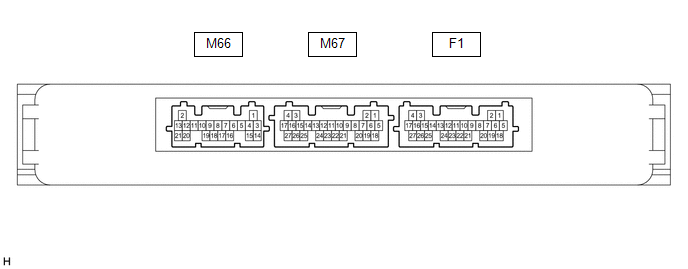
(a) Disconnect the F1 connector from the certification ECU (smart key ECU assembly).
(b) Measure the voltage and resistance according to the value(s) specified in the table below.
Terminal No. (Symbol) | Wire Color | Terminal Description | Condition | Specified Condition |
|---|---|---|---|---|
F1-4 (+B) - Body ground |
L - Body ground |
Battery power supply |
Always |
11 à 14 V |
F1-18 (E) - Body ground |
W-B - Body ground |
Ground |
Always |
Below 1 Ω |
(c) Reconnect connector M67 of the certification ECU (smart key ECU assembly).
(d) Check the pulses according to the values shown in the table below.
Terminal No. (Symbol) | Wire Color | Terminal Description | Condition | Specified Condition |
|---|---|---|---|---|
M67-26 (TSW5) - Body ground |
LG - Body ground |
Back door opener switch input |
Trunk door opener switch assembly (opener switch) OFF → ON |
Below 1 V → pulse generation |
CHECK DOUBLE LOCK CONTROL RELAY ASSEMBLY (without Toyota Safety Sense P)

(a) Disconnect connector F14 of the double lock control relay assembly.
(b) Measure the voltage and resistance according to the value(s) specified in the table below.
Terminal No. (Symbol) | Wire Color | Terminal Description | Condition | Specified Condition |
|---|---|---|---|---|
F14-12 (+B) - Body ground |
BE - Body ground |
Battery power supply |
Ignition Switch in OFF position |
11 à 14 V |
F14-11 (CPUB) - Body ground |
SB - Body ground |
Battery power supply |
Ignition Switch in OFF position |
11 à 14 V |
F14-7 (GND) - Body ground |
LA - Body ground |
Ground |
Always |
Below 1 Ω |
(c) Reconnect connector F14 of the double lock control relay assembly.
(d) Measure the voltage and check the pulses according to the value(s) in the table below.
Terminal No. (Symbol) | Wire Color | Terminal Description | Condition | Specified Condition |
|---|---|---|---|---|
F14-8 (ACTS) - Body ground |
LG - Body ground |
Output voltage when the all-door double lock motor is activated |
Double lock disabled |
Below 1 V |
F14-8 (ACTS) - Body ground |
LG - Body ground |
Output voltage when the all-door double lock motor is activated |
Double lock enabled |
11 à 14 V |
F14-1 (ACTR) - Body ground |
GR - Body ground |
Output voltage when the all-door lock motor is deactivated |
Double lock enabled |
Below 1 V |
F14-1 (ACTR) - Body ground |
GR - Body ground |
Output voltage when the all-door lock motor is deactivated |
Double lock disabled |
11 à 14 V |
F14-6 (DLPD) - Body ground |
Y - Body Ground |
Front right double lock position switch input voltage |
Double lock disabled |
Pulse generation |
F14-6 (DLPD) - Body ground |
Y - Body Ground |
Front right double lock position switch input voltage |
Double lock enabled |
Below 1 V |
F14-5 (DLPP) - Body ground |
V - Body ground |
Front left double lock position switch input |
Double lock disabled |
Pulse generation |
F14-5 (DLPP) - Body ground |
V - Body ground |
Front left double lock position switch input |
Double lock enabled |
Below 1 V |
F14-4 (DLPR) - Body ground |
B - Body ground |
Rear right double lock position switch input |
Double lock disabled |
Pulse generation |
F14-4 (DLPR) - Body ground |
B - Body ground |
Rear right double lock position switch input |
Double lock enabled |
Below 1 V |
F14-3 (DLPL) - Body ground |
L - Body ground |
Rear left double lock position switch input voltage |
Double lock disabled |
Pulse generation |
F14-3 (DLPL) - Body ground |
L - Body ground |
Rear left double lock position switch input voltage |
Double lock enabled |
Below 1 V |