Door Lock
System Diagram
In this manual: Door Lock
~1min read
SYSTEM DIAGRAM
Door Lock Control System
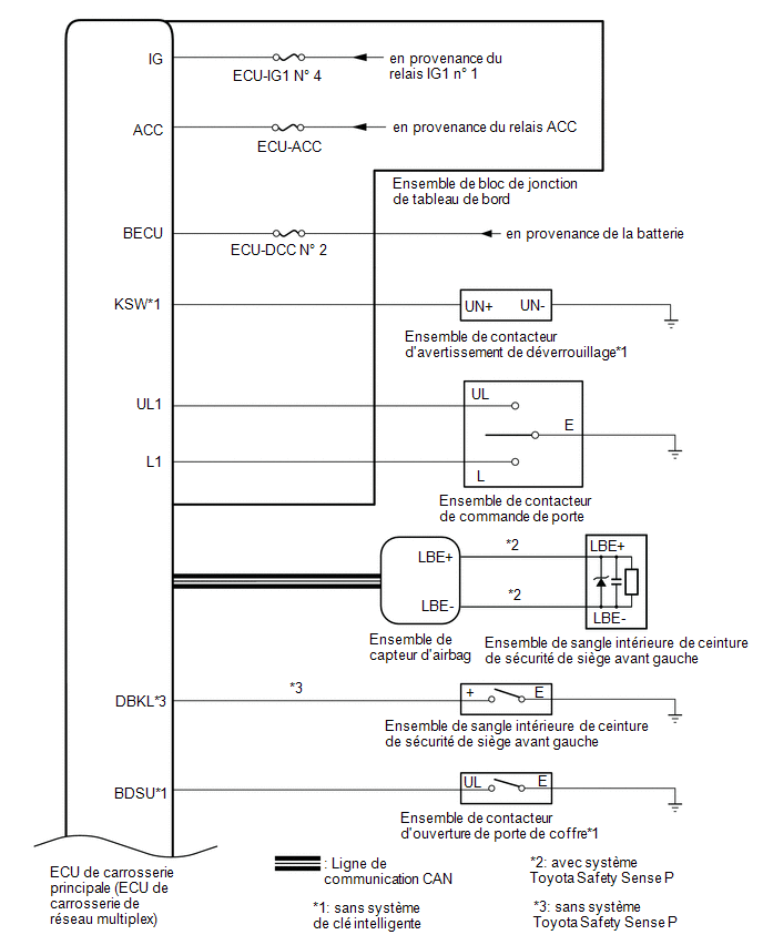
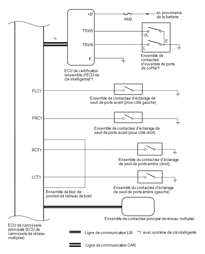
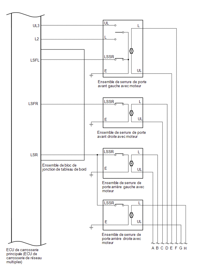
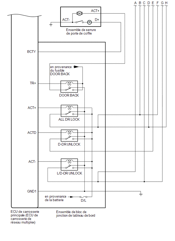 Communication Table
Transmitter | Receiver | Signal | Line |
|---|---|---|---|
Multiplex Network Master Switch Assembly |
Main body ECU (multiplex network body ECU) |
Door Control Switch Signal |
LIN |
Certification ECU (smart key ECU assembly)*1 |
Main body ECU (multiplex network body ECU) |
Back Door Opening Switch Signal |
CAN |
Airbag ECU Assembly*2 |
Main body ECU (multiplex network body ECU) |
Front LH Seat Belt Inner Buckle Switch Assembly |
CAN |
- *1: with Smart Key System
- *2: with Toyota Safety Sense P system
Double Locking System (w/o Toyota Safety Sense P)
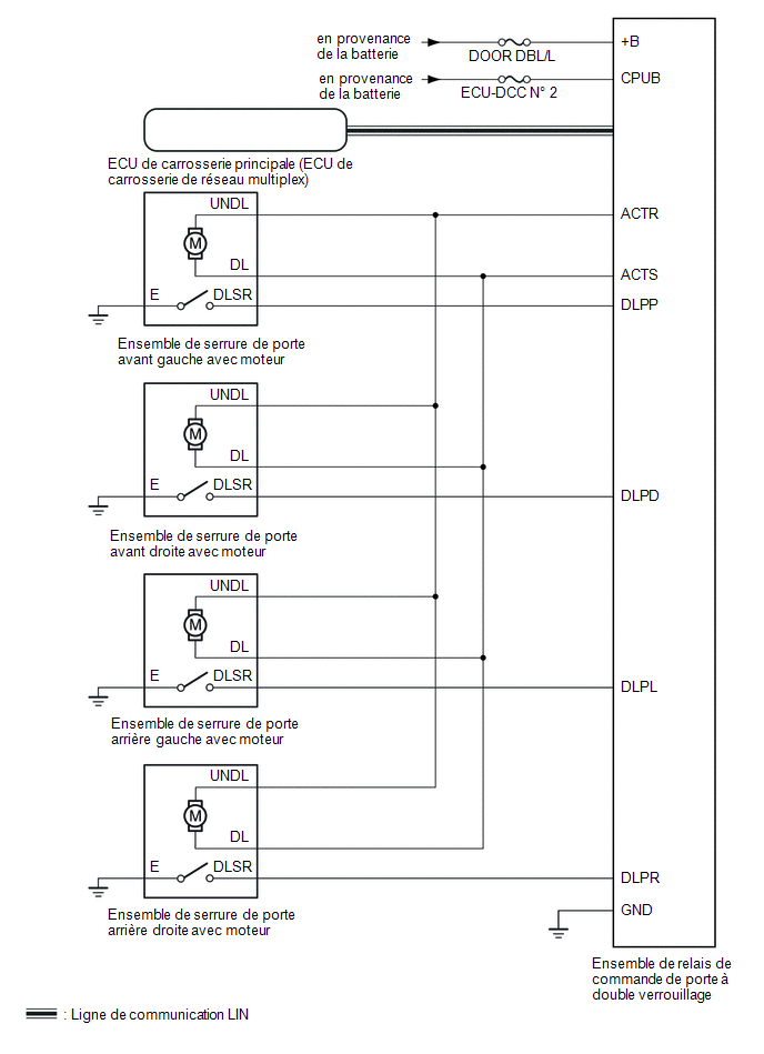 Communication Table
Transmitter | Receiver | Signal | Line |
|---|---|---|---|
Double Locking Door Control Relay Assembly |
Main body ECU (multiplex network body ECU) |
Double Locking Position Switch Signal |
LIN |
Main body ECU (multiplex network body ECU) |
Double Locking Door Control Relay Assembly |
Double Locking Enable/Disable Request Signal |
LIN |
Was this page helpful?