LIN Communication Bus Malfunction (B2325)
DESCRIPTION
If the main body ECU (multiplex network body ECU) detects a communication error with an ECU connected to the door bus lines for at least 7 seconds, DTC B2325 is stored.
DTC No. | Detection Item | DTC Detection Condition | Suspected Area |
|---|---|---|---|
B2325 |
LIN Communication Bus Malfunction |
The main body ECU (multiplex network body ECU) detects a communication error with an ECU connected to the door bus lines for at least 7 seconds. |
|
- *1: with double lock system
WIRING DIAGRAM
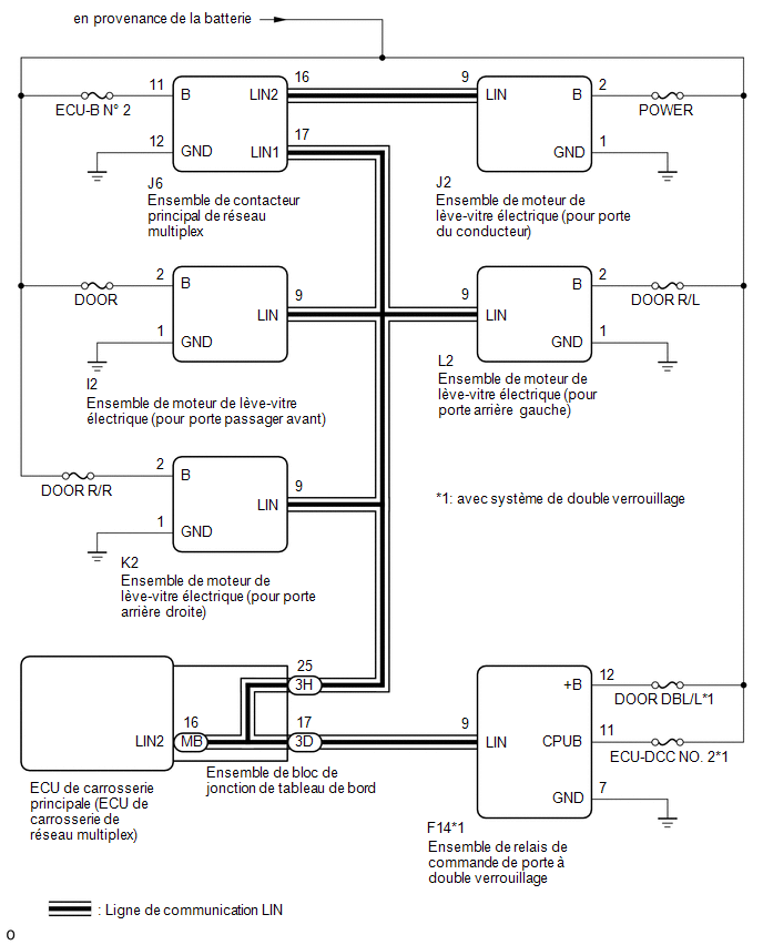
PRECAUTION / NOTICE / HINT
NOTICE:
- Check the fuses for the circuits related to this system before performing the following procedure.
- When a power window motor assembly is replaced, or removed and reinstalled, initialization must be performed.
Click here

- Before performing the inspection, make sure that DTC B1206, B1249, B2321, B2322, B2323 or B2324 is not output.
Click here
- If the Main Body ECU (Multiplex Network Body ECU) has been replaced, refer to the registration section.*1
Click here
- *1: with Smart Key System
PROCEDURE
INSPECT INSTRUMENT PANEL JUNCTION BLOCK ASSEMBLY
(a) Remove the instrument panel junction block assembly.
Click here
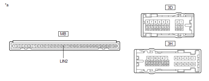
*a |
Component without wire harness connected (instrument panel junction block assembly) |
- |
- |
(b) Remove the main body ECU (multiplex network body ECU) from the instrument panel junction block assembly.
(c) Measure the resistance according to the value(s) in the table below.
HINT:
This check is used to inspect the LIN communication line in the instrument panel junction block assembly that connects the wire harness to the integrated main body ECU (multiplex network body ECU).
Standard resistance:
Tester Connection | Condition | Specified Condition |
|---|---|---|
3H-25 - MB-16 (LIN2) |
Always |
Below 1 Ω |
3D-17 - MB-16 (LIN2) |
Always |
Below 1 Ω |
| NG |  |
REPLACE INSTRUMENT PANEL JUNCTION BLOCK ASSEMBLY |
|

CHECK HARNESS AND CONNECTOR (INSTRUMENT PANEL JUNCTION BLOCK ASSEMBLY - EACH ECU)
(a) Disconnect the J2 connector from the power window motor assembly (for driver door).
(b) Disconnect the I2 connector from the power window regulator motor assembly (for front passenger door).
(c) Disconnect the L2 connector from the power window regulator motor assembly (for RR door LH).
(d) Disconnect the K2 connector from the power window regulator motor assembly (for RR door RH).
(e) Disconnect the J6 connector from the multiplex network main switch assembly.
(f) Disconnect the F14 connector from the double locking door control relay assembly.*1
(g) Measure the resistance according to the value(s) specified in the table below.
NOTICE:
Make sure that each ECU is in sleep mode before performing the check. To enter sleep mode, turn the ignition switch from ON to OFF and wait at least 180 seconds without operating any switches.
Standard resistance:
Tester Connection | Ignition switch position | Specified Condition |
|---|---|---|
3H-25 - J6-17 (LIN1) |
Ignition Switch in OFF position |
Below 1 Ω |
3D-17 - F14-9 (LIN)*1 |
Ignition Switch in OFF position |
Below 1 Ω |
3H-25 - I2-9 (LIN) |
Ignition Switch in OFF position |
Below 1 Ω |
3H-25 - L2-9 (LIN) |
Ignition Switch in OFF position |
Below 1 Ω |
3H-25 - K2-9 (LIN) |
Ignition Switch in OFF position |
Below 1 Ω |
3H-25 - J2-9 (LIN) |
Ignition Switch in OFF position |
Below 1 Ω |
J6-17 (LIN1) - Body Ground |
Ignition Switch in OFF position |
10 kΩ minimum |
F14-9 (LIN) - Body ground*1 |
Ignition Switch in OFF position |
10 kΩ minimum |
3H-25 or 3D-17 - Body ground |
Ignition Switch in OFF position |
10 kΩ minimum |
I2-9 (LIN) - Body Ground |
Ignition Switch in OFF position |
10 kΩ minimum |
L2-9 (LIN) - Body Ground |
Ignition Switch in OFF position |
10 kΩ minimum |
K2-9 (LIN) - Body Ground |
Ignition Switch in OFF position |
10 kΩ minimum |
J2-9 (LIN) - Body Ground |
Ignition Switch in OFF position |
10 kΩ minimum |
- *1: with double lock system
| NG | |
REPAIR OR REPLACE HARNESS OR CONNECTOR |
|
CHECK POWER WINDOW REGULATOR MOTOR ASSEMBLY (rear LH door)
(a) Reconnect the 3D and 3H connectors to the instrument panel junction block assembly.
(b) Reconnect the J2 connector to the power window regulator motor assembly (for driver door).
(c) Reconnect the I2 connector to the power window motor assembly (for front passenger door).
(d) Reconnect the K2 connector to the power window regulator motor assembly (for RR door RH).
(e) Reconnect the J6 connector to the multiplex network main switch assembly.
(f) Reconnect the F14 connector to the double locking door control relay assembly.*1
(g) Clear the DTCs.
Click here
(h) After 10 seconds have elapsed, check whether the same DTC is output again.
Body Electrical > Main Body > Trouble Codes- *1: with double lock system
Result:
Result | Proceed to |
|---|---|
DTC B2325 is output |
A |
DTC B2325 is not output |
B |
| B | |
REPLACE POWER WINDOW REGULATOR MOTOR ASSEMBLY (for Rear Door LH) |
|
INSPECT MULTIPLEX NETWORK MAIN SWITCH ASSY
(a) Reconnect the L2 connector to the power window regulator motor assembly (for RR door LH).
(b) Disconnect the J6 connector from the multiplex network main switch assembly.
(c) Clear the DTCs.
Click here
(d) After 10 seconds have elapsed, check whether the same DTC is output again.
Body Electrical > Main Body > Trouble CodesResult:
Result | Proceed to |
|---|---|
DTC B2325 is output |
A |
DTC B2325 is not output |
B |
| B | |
REPLACE MULTIPLEX NETWORK MAIN SWITCH ASSEMBLY |
|
CHECK POWER WINDOW REGULATOR MOTOR ASSEMBLY (for rear RH door)
(a) Reconnect the J6 connector to the multiplex network main switch assembly.
(b) Disconnect the K2 connector from the power window regulator motor assembly (for RR door RH).
(c) Clear the DTCs.
Click here
(d) After 10 seconds have elapsed, check whether the same DTC is output again.
Body Electrical > Main Body > Trouble CodesResult:
Result | Proceed to |
|---|---|
DTC B2325 is output |
A |
DTC B2325 is not output |
B |
| B | |
REPLACE POWER WINDOW REGULATOR MOTOR ASSEMBLY (for RR door RH) |
|
CHECK POWER WINDOW REGULATOR MOTOR ASSEMBLY (for driver door)
(a) Reconnect the K2 connector to the power window regulator motor assembly (for RR door RH).
(b) Disconnect connector J2 from the power window motor assembly (for driver door).
(c) Clear the DTCs.
Click here
(d) After 10 seconds have elapsed, check whether the same DTC is output again.
Body Electrical > Main Body > Trouble CodesResult:
Result | Proceed to |
|---|---|
DTC B2325 is output |
A |
DTC B2325 is not output |
B |
| B | |
REPLACE POWER WINDOW REGULATOR MOTOR ASSEMBLY (for driver side) |
|
CHECK FRONT POWER WINDOW REGULATOR MOTOR ASSEMBLY (for front passenger side)
(a) Reconnect connector J2 of the power window regulator motor assembly (for driver door).
(b) Disconnect the I2 connector from the power window regulator motor assembly (for front passenger door).
(c) Clear the DTCs.
Click here
(d) After 10 seconds have elapsed, check whether the same DTC is output again.
Body Electrical > Main Body > Trouble CodesResult:
Result | Proceed to |
|---|---|
DTC B2325 is output (with double lock system) |
A |
DTC B2325 is output (without double lock system) |
B |
DTC B2325 is not output |
C |
| B | |
REPLACE MAIN BODY ECU (MULTIPLEX NETWORK BODY ECU) |
| C | |
REPLACE POWER WINDOW REGULATOR MOTOR ASSEMBLY (for front passenger side) |
|
CHECK DOUBLE LOCK CONTROL DOOR RELAY ASSY
(a) Reconnect all ECU connectors.
(b) Disconnect connector F14 of the double lock control door relay assembly.
(c) Clear the DTCs.
Click here
(d) After 10 seconds have elapsed, check whether the same DTC is output again.
Body Electrical > Main Body > Trouble CodesResult:
Result | Proceed to |
|---|---|
DTC B2325 is output |
A |
DTC B2325 is not output |
B |
| A | |
REPLACE MAIN BODY ECU (MULTIPLEX NETWORK BODY ECU) |
| B | |
REPLACE DOUBLE LOCK CONTROL DOOR RELAY ASSY |