Brake master cylinder sub-assy
- REMOVE AIR CLEANER ASSY
- REMOVE BRAKE MASTER CYLINDER SUB−ASSY
Disconnect the level warning switch connector.
w/o ABS: Using SST, disconnect the 5 brake tubes from the brake master cylinder.
SST 09023−00101
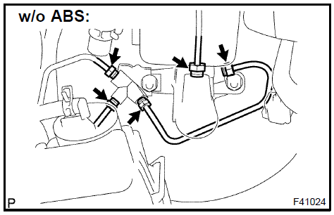
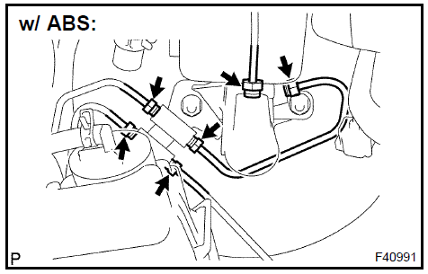
w/ ABS: Using SST, disconnect the 6 brake tubes from the brake master cylinder.
SST 09023−00101

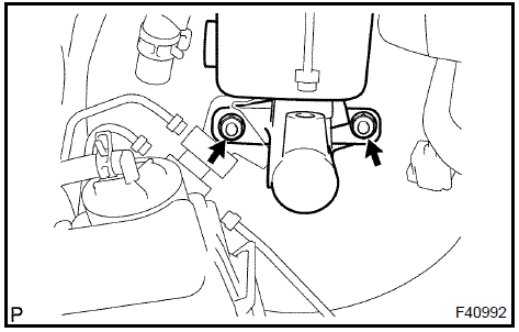
w/o ABS: Remove the 2 nuts, pull out the 3−way and brake master cylinder sub−assy.
w/ ABS: Remove the 2 nuts, pull out the 2−way and brake master cylinder sub−assy.
Pull out the master cylinder reservoir filler cap assy.
Pull out the master cylinder reservoir strainer.
Remove the screw and pull out the master cylinder reservoir sub−assy.
Remove the 2 master cylinder reservoir grommets.
Place master cylinder in vise.
Remove the O−ring.
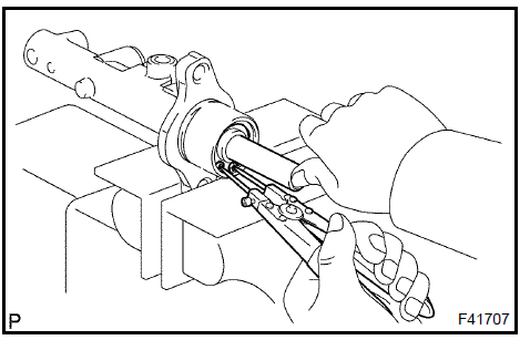
Push in the piston and remove the snap ring with snap ring pliers.
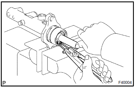
Push in the piston and remove the piston stopper bolt and gasket.
Remove the No.1 piston sub−assy, pulling straight out not at an angle.
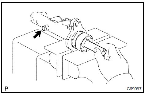
Place a waste cloth and 2 wooden blocks on the work table and lightly edges until the No.2 piston sub−assy drops out of the cylinder.
HINT: Make sure the distance a from the rag the top of the blocks is at least 100 mm (3.94 in.).
NOTICE: If pulled out at an angle, there is a possibility that the cylinder bore could be damaged.
Place master cylinder in vise.
Remove the O−ring.
Push in the piston and remove the snap ring with snap ring pliers.
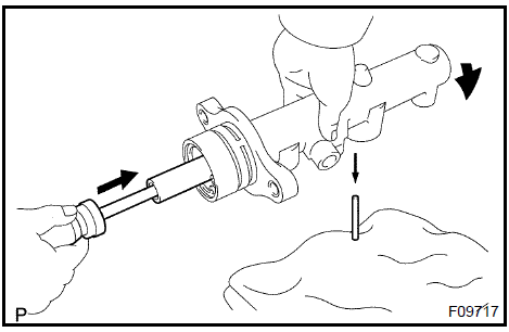
Push in the piston with a screwdriver, and remove the straight pin by turning over the cylinder body.
HINT: Tape the screwdriver tip before use.
Remove the No.1 and No.2 piston sub−assy and 2 springs by hand, pulling straight out, not at an angle.
Check the cylinder bore for rust or scoring.
Place master cylinder in vise.
Apply the lithium soap base grycol grease on new No.1 and No.2 piston sub−assy.
Install the No.2 and No.1 piston sub−assy.
- If the piston is inserted at an angle, there is a possibility that the cylinder bore could be damaged.
- Be careful not to damage the rubber lips on the pistons.
Push in the piston and install a new gasket and a new piston stopper bolt.
Torque: 10 N·m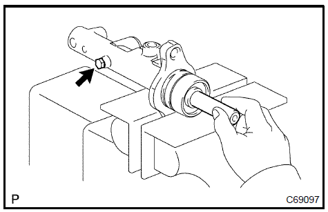
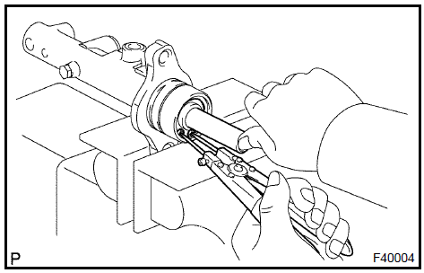
Push in the piston and install the snap ring with snap ring pliers.
Apply the lithium soap base grycol grease on a new O− ring and install the O−ring to the master cylinder.
Place master cylinder in vise.
Apply the lithium soap base glycol grease on new No.1 and No.2 piston sub−assy.
Install the No.2 and No.1 piston sub−assy.
- If the piston is inserted at an angle, there is a possibility that the cylinder bore could be damaged.
- Be careful not to damage the rubber lips on the pistons.
Install the straight pin.
HINT: Insert the No.2 piston with the groove positioning horizontally.
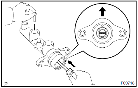
Push in the piston and install the snap ring with snap ring pliers.
Apply the lithium soap base glycol grease on a new O− ring and install the O−ring to the master cylinder.
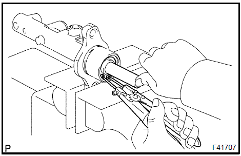
Apply the lithium soap base glycol grease on the 2 master cylinder reservoir grommets.
Install the 2 master cylinder reservoir grommets to the master cylinder reservoir sub−assy.
Install the master cylinder reservoir sub−assy to the master cylinder with the screw.
Install the brake master cylinder reservoir strainer.
Install the brake master cylinder reservoir filler cap assy.
Apply SST to the master cylinder.
SST 09737−00013
Set SST, on the master cylinder, lower the pin of the SST until it slightly touches the piston.
Apply the chalk to the flat surfaced tip of the SST pin.
Turn SST upside down and place it clearance between the brake booster and SST.
Clearance: 0 mm (0 in.)
HINT:
If there is a clearance between the SST main body and the booster shell. It means that the specified value, and no chalk attachment on the booster push rod means that it is more than the specified value.
Brake booster push rod clearance before shipment is adjusted to be 0.105 mm ( 0.004 in.).
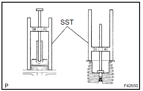
Using SST, adjust the booster push rod length until the push rod lightly touches the pin head.
SST 09737−00020
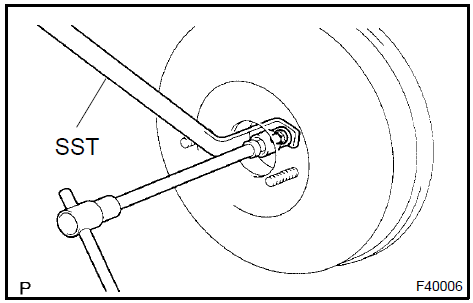
w/o ABS: Install the master cylinder sub−assy and 3−way with the 2 nuts.
Torque: 13 N·mw/ ABS: Install the master cylinder sub−assy and 2−way with the 2 nuts.
Torque: 13 N·m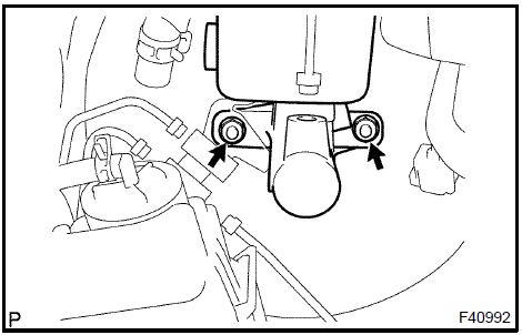
w/o ABS: Using SST and connect the 5 brake tubes to the master cylinder sub−assy.
SST 09023−00101 Torque: 15 N·m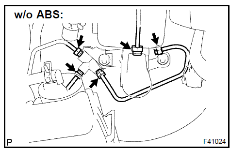
w/ ABS: Using SST and connect the 6 brake tubes to the master cylinder sub−assy.
SST 09023−00101
Torque: 15 N·mConnect the level warning switch connector.
- FILL RESERVOIR WITH BRAKE FLUID
- BLEED MASTER CYLINDER
SST 09023−00101
- BLEED BRAKE LINE
- INSTALL AIR CLEANER ASSY
- CHECK FLUID LEVEL IN RESERVOIR
- CHECK BRAKE FLUID LEAKAGE
Test yourself
A quick Toyota Camry quiz: every answer comes with an explanation and a link to the manual page.