Starter Signal Circuit
1. w/o Smart Key System
While the engine is being cranked, current flows from terminal ST1 of the ignition switch assembly to the park/neutral position switch assembly and also flows to terminal STA of the ECM (STA Signal).
2. w/ Smart Key System
While the engine is being cranked, current flows from terminal STAR of the power management control ECU to the park/neutral position switch assembly and also flows to terminal STA of the ECM (STA signal).
WIRING DIAGRAM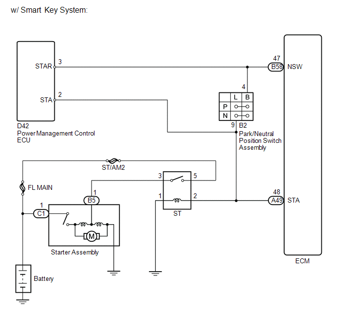
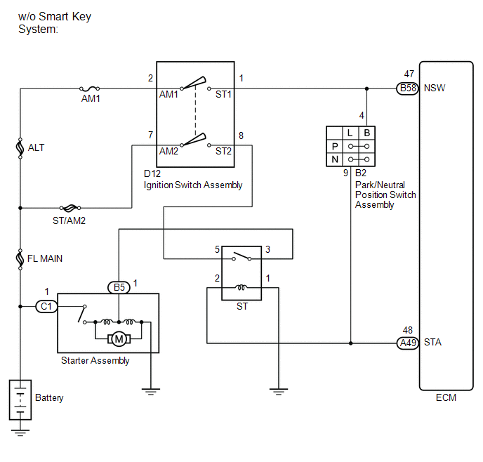
CAUTION / NOTICE / HINT
NOTICE:
Inspect the fuses for circuits related to this system before performing the following inspection procedure.
PROCEDUREREAD VALUE USING TECHSTREAM (STARTER SIGNAL)
(a) Connect the Techstream to the DLC3.
(b) Turn the ignition switch to ON.
(c) Turn the Techstream on.
(d) Enter the following menus: Powertrain / Engine / Data List / Starter Signal.
(e) Read the value displayed on the Techstream when the ignition switch is turned to ON and the engine is started.
OK:
Condition | Techstream Display |
|---|---|
Ignition switch ON |
OFF (starter signal OFF) |
Engine started |
ON (starter signal ON) |
| OK |  | PROCEED TO NEXT SUSPECTED AREA SHOWN IN PROBLEM SYMPTOMS TABLE |
|

CHECK ST RELAY (POWER SOURCE)
(a) Inspect the ST relay (See page  ).
Result | Proceed to |
|---|---|
OK |
A |
NG (w/o Smart Key System) |
B |
NG (w/ Smart Key System) |
C |
| A | | REPAIR OR REPLACE HARNESS OR CONNECTOR (ECM - PARK/NEUTRAL POSITION SWITCH ASSEMBLY) |
| C | | GO TO STEP 7 |
|
CHECK HARNESS AND CONNECTOR (ST RELAY - PARK/NEUTRAL POSITION SWITCH ASSEMBLY - ECM)
(a) Remove the ST relay from the engine room relay block.
(b) Disconnect the park/neutral position switch assembly connector.
(c) Disconnect the ECM connector.
(d) Measure the resistance according to the value(s) in the table below.
Standard Resistance (Check for Open):
Tester Connection | Condition | Specified Condition |
|---|---|---|
2 (ST relay terminal) - B2-9 (L) |
Always |
Below 1 Ω |
2 (ST relay terminal) - A49-48 (STA) |
Always |
Below 1 Ω |
Standard Resistance (Check for Short):
Tester Connection | Condition | Specified Condition |
|---|---|---|
2 (ST relay terminal) or B2-9 (L) - Body ground |
Always |
10 kΩ or higher |
2 (ST relay terminal) or A49-48 (STA) - Body ground |
Always |
10 kΩ or higher |
| NG | | REPAIR OR REPLACE HARNESS OR CONNECTOR (ST RELAY - PARK/NEUTRAL POSITION SWITCH ASSEMBLY - ECM) |
|
INSPECT PARK/NEUTRAL POSITION SWITCH ASSEMBLY
(a) Inspect the park/neutral position switch assembly (See page for U760E, See page for U760F).
Result | Proceed to |
|---|---|
OK |
A |
NG (for U760E) |
B |
NG (for U760F) |
C |
| B | | REPLACE PARK/NEUTRAL POSITION SWITCH ASSEMBLY |
| C | | REPLACE PARK/NEUTRAL POSITION SWITCH ASSEMBLY |
|
CHECK HARNESS AND CONNECTOR (IGNITION SWITCH - ECM - PARK/NEUTRAL POSITION SWITCH)
(a) Disconnect the ignition switch assembly connector.
(b) Disconnect the park/neutral position switch assembly connector.
(c) Disconnect the ECM connector.
(d) Measure the resistance according to the value(s) in the table below.
Standard Resistance (Check for Open):
Tester Connection | Condition | Specified Condition |
|---|---|---|
D12-1 (ST1) - B58-47 (NSW) |
Always |
Below 1 Ω |
D12-1 (ST1) - B2-4 (B) |
Always |
Below 1 Ω |
Standard Resistance (Check for Short):
Tester Connection | Condition | Specified Condition |
|---|---|---|
D12-1 (ST1) or B58-47 (NSW) - Body ground |
Always |
10 kΩ or higher |
D12-1 (ST1) or B2-4 (B) - Body ground |
Always |
10 kΩ or higher |
| NG | | REPAIR OR REPLACE HARNESS OR CONNECTOR (IGNITION SWITCH - ECM - PARK/NEUTRAL POSITION SWITCH) |
|
INSPECT IGNITION SWITCH ASSEMBLY
(a) Inspect the ignition switch assembly (See page ).
| OK | | REPAIR OR REPLACE HARNESS OR CONNECTOR (IGNITION SWITCH ASSEMBLY - BATTERY) |
| NG | | REPLACE IGNITION SWITCH ASSEMBLY |
CHECK HARNESS AND CONNECTOR (ST RELAY - POWER MANAGEMENT CONTROL ECU - PARK/NEUTRAL POSITION SWITCH ASSEMBLY - ECM)
(a) Disconnect the ECM connector.
(b) Disconnect the park/neutral position switch assembly connector.
(c) Disconnect the power management control ECU connector.
(d) Remove the ST relay from the engine room relay block.
(e) Measure the resistance according to the value(s) in the table below.
Standard Resistance (Check for Open):
Tester Connection | Condition | Specified Condition |
|---|---|---|
2 (ST relay terminal ) or A49-48 (STA) |
Always |
Below 1 Ω |
2 (ST relay terminal) - B2-9 (L) |
Always |
Below 1 Ω |
2 (ST relay terminal) - D42-2 (STA) |
Always |
Below 1 Ω |
Standard Resistance (Check for Short):
Tester Connection | Condition | Specified Condition |
|---|---|---|
2 (ST relay terminal ) or A49-48 (STA) - Body ground |
Always |
10 kΩ or higher |
2 (ST relay terminal ) or B2-9 (L) - Body ground |
Always |
10 kΩ or higher |
2 (ST relay terminal ) or D42-2 (STA) - Body ground |
Always |
10 kΩ or higher |
| NG | | REPAIR OR REPLACE HARNESS OR CONNECTOR (ST RELAY - POWER MANAGEMENT CONTROL ECU - PARK/NEUTRAL POSITION SWITCH ASSEMBLY - ECM) |
|
INSPECT PARK/NEUTRAL POSITION SWITCH ASSEMBLY
(a) Inspect the park/neutral position switch assembly (See page for U760E, See page for U760F).
Result | Proceed to |
|---|---|
OK |
A |
NG (for U760E) |
B |
NG (for U760F) |
C |
| B | | REPLACE PARK/NEUTRAL POSITION SWITCH ASSEMBLY |
| C | | REPLACE PARK/NEUTRAL POSITION SWITCH ASSEMBLY |
|
CHECK HARNESS AND CONNECTOR (POWER MANAGEMENT CONTROL ECU - ECM - PARK/NEUTRAL POSITION SWITCH ASSEMBLY)
(a) Disconnect the power management control ECU connector.
(b) Disconnect the ECM connector.
(c) Disconnect the park/neutral position switch assembly connector.
(d) Measure the resistance according to the value(s) in the table below.
Standard Resistance (Check for Open):
Tester Connection | Condition | Specified Condition |
|---|---|---|
D42-3 (STAR) - B58-47 (NSW) |
Always |
Below 1 Ω |
D42-3 (STAR) - B2-4 (B) |
Always |
Below 1 Ω |
Standard Resistance (Check for Short):
Tester Connection | Condition | Specified Condition |
|---|---|---|
D42-3 (STAR) or B58-47 (NSW) - Body ground |
Always |
10 kΩ or higher |
D42-3 (STAR) or B2-4 (B) - Body ground |
Always |
10 kΩ or higher |
| OK | | GO TO SMART KEY SYSTEM |
| NG | | REPAIR OR REPLACE HARNESS OR CONNECTOR (POWER MANAGEMENT CONTROL ECU - ECM - PARK/NEUTRAL POSITION SWITCH ASSEMBLY) |
Test yourself
A quick Toyota Venza quiz: every answer comes with an explanation and a link to the manual page.