Connecting Rod and Piston Assembly
PROCEDURE
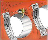
Piston Cooling Nozzle Installation
Remove and disassemble the connecting rod and piston assembly in the same way as on 1.1 and 1.3 L engines. Inspect, check and repair in the same way as on 1.1 and 1.3 L engines.
Specifications that differ are listed below.
The maximum side clearance between the rings and piston grooves (see figure: Measuring Piston Ring Side Clearance) is 0.20 mm for compression rings and 0.15 mm for oil control rings. Measure the ring end gap at 20 mm from the bottom of the cylinder. On turbocharged diesel engines, remove the piston cooling nozzles shown in figure: Piston Cooling Nozzle Installation before measuring the end gap. Compression ring end gap is 0.3–0.5 mm; oil control ring end gap is 0.25–0.4 mm.
Maximum permissible clearance is 1.0 mm.
Maximum permissible piston-to-cylinder clearance is 0.07 mm. Pistons of turbocharged diesel engines have a recess on one side of the skirt, which prevents the piston from striking the nozzle when the piston is at BDC. In engines with hydraulic valve lifters, the pistons of cylinders 2 and 3 have 15° chamfers. Assemble the piston and connecting rod assembly in the same way as on 1.1 and 1.3 L engines, taking into account the following: 1. The arrow on the piston crown (see figure: Piston Crown Mark and Connecting Rod and Cap Projections) must point toward the camshaft drive, and the projections on the connecting rod and cap must face the intermediate shaft side. 2. On turbocharged engines, the skirt recess must be on the piston cooling nozzle side. 3. On engines with hydraulic valve lifters, the pistons of cylinders 2 and 3 must have 15° chamfers. 4. Replace the connecting rod bolts and nuts. 5. Piston cooling nozzle mounting bolt torque 10 N·m. Connecting rod bolt torque: – M9x1x15 bolt – 50 N·m; – M8x1x25 bolt (stretch bolt): – Stage 1 – 30 N·m; – Stage 2 – tighten a further half turn (180°).
Test yourself
A quick Volkswagen Golf quiz: every answer comes with an explanation and a link to the manual page.