Camshaft Drive
PROCEDURE
In January 1984 the design of the camshaft drive covers was changed. In connection with this, the intermediate shaft pulley and the front high-pressure fuel pump (HPFP) bracket were changed. The intermediate shaft pulley was moved closer to the cylinder block, so the new HPFP bracket has a recess at the location of the intermediate shaft pulley.
Clearance between the intermediate shaft pulley and the high-pressure fuel pump bracket
Only the new intermediate shaft pulley is supplied as a spare part, therefore when installing it on engines produced before January 1984
ensure a clearance of 0.5 mm between the pulley and the HPFP bracket, as shown in the figure.
If necessary, file down the flange of the bracket at the pulley location. Engines are fitted with two variants of camshaft drive covers, and the camshaft drive belt is either fully or partially enclosed.
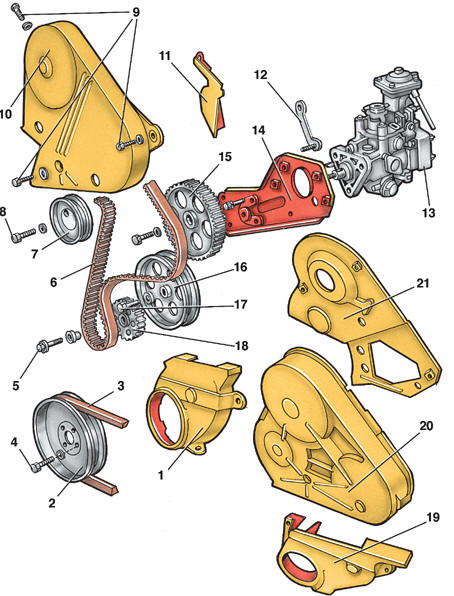
Camshaft drive components 1 – lower camshaft drive cover; 2 – alternator drive belt; 3 – crankshaft pulley; 4 – crankshaft pulley bolt; 5 – crankshaft gear bolt; 6 – camshaft drive belt; 7 – tensioner; 8 – tensioner mounting nut; 9 – upper cover mounting bolt; 10 – upper camshaft drive cover; 11 – rear camshaft drive cover; 12 – rear fuel pump mounting bracket; 13 – high-pressure fuel pump; 14 – front fuel pump mounting bracket; 15 – fuel pump gear; 16 – intermediate shaft pulley; 17 – pulley mounting bolt; 18 – crankshaft gear; 19 – lower camshaft drive cover (fully enclosed drive variant); 20 – upper camshaft drive cover (fully enclosed drive variant); 21 – rear camshaft drive cover (fully enclosed drive variant)
Disassembly PROCEDURE 1. Loosen the alternator mounting bolts. Pivot the alternator toward the cylinder block and remove the alternator drive belt 2 (see figure Camshaft drive components). 2. Unscrew bolts 9 and remove the upper cover 10. 3. Remove the cylinder head cover.
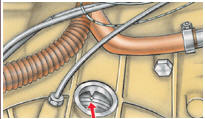
4. Set the piston of the new cylinder to TDC of the compression stroke. To do this, remove the plastic plug from the top of the clutch housing and turn the crankshaft so that the TDC mark on the flywheel aligns with the boss on the clutch housing, as shown in the figure.
The cams of the No. 1 cylinder camshaft, counting from the camshaft drive, must point upward. The slot on the rear end of the camshaft must be positioned horizontally.
Warning: Turn the crankshaft only by the crankshaft gear bolt.
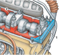
5. Lock the camshaft (2) with the special tool (1), as shown in the figure. To do this, insert the tab of the tool into the slot on the end of the camshaft. Turn the camshaft so that one end of the tool rests on the cylinder head. Measure the clearance between the other end of the tool and the cylinder head with a feeler gauge. Insert a feeler gauge of thickness equal to half the measured clearance into the gap.
Turn the camshaft so that the end of the tool rests on the feeler gauge, then insert a feeler gauge of the same thickness between the other end of the tool and the cylinder head. Do not remove the tool, since the camshaft must remain locked during installation of the drive.
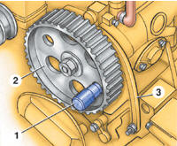
6. Lock the gear (2) of the high-pressure fuel pump by screwing the special pin (1) into the threaded hole of the gear, as shown in the illustration (3 – front fuel pump mounting bracket). 7. Unscrew bolts 4 (see illustration Camshaft Drive Components) and remove crankshaft pulley 3. 8. Remove the lower camshaft drive cover 1. 9. Loosen nut 8 and, using the special wrench, turn tensioner 7 counterclockwise to release the tension of belt 6. 10. Remove camshaft drive belt 6. 11. Unscrew nut 8 and remove tensioner 7. 12. Unscrew the camshaft gear bolt and, tapping the gear with a rubber mallet, remove it from the camshaft. If the engine has covers that fully enclose the camshaft drive, insert a 6 mm diameter pin into the hole of cover 21 and drive the camshaft gear off with a hammer using this pin. 13. Unscrew bolt 5 and remove crankshaft gear 18. 14. Unscrew bolt 17 and remove intermediate shaft pulley 16. Remove the key from the intermediate shaft keyway. 15. Using a special puller, remove fuel pump gear 15. Remove the key. 16. To remove rear cover 21, remove the high-pressure fuel pump and front fuel pump mounting bracket 14. Installation PROCEDURE 1. If rear cover 21 was removed, install the cover, bracket 14 and fuel pump 13. 2. Install the key into the fuel pump shaft keyway, install gear 15, install the gear retaining nut and tighten to 45 N·m. 3. Install the key into the intermediate shaft keyway, install intermediate shaft pulley 16, install bolt 17 with washer and tighten to 45 N·m. 4. Install gear 18 so that the protrusion of the gear engages the groove on the crankshaft. Install bolt 5 and tighten to 180 N·m if the bolt has a hex head. From March 1988, bolts with a twelve-point head are fitted; tighten to 90 N·m, then turn an additional half turn (180°). Twelve-point head bolts must not be reused. Before installing, apply “D6” thread locking compound to the bolt threads. 5. Install tensioner 7, install nut 8 with washer. Do not tighten nut 8. 6. Install camshaft gear, install the gear bolt with washer, do not tighten. 7. Check that the TDC marks on the flywheel and clutch housing align.
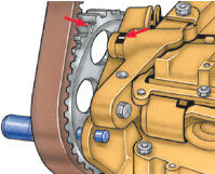
8. Turn the fuel pump gear so that the marks on the gear and the fuel pump bracket align, as shown in the illustration.
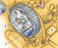
9. Lock the gear (2) of the high-pressure fuel pump by screwing the special pin (1) into the threaded hole of the gear, as shown in the illustration (3 – front fuel pump mounting bracket). 10. Install belt 6 (see illustration Camshaft Drive Components) onto the camshaft, crankshaft, fuel pump gears, intermediate shaft pulleys and tensioner. 11. Tighten the camshaft gear bolt to 45 N·m. 12. Remove the locking pin from the fuel pump gear. 13. Install tension gauge tool VW 210 on belt 6, after setting its scale to 12–13 units.
Install the tool midway between the camshaft and fuel pump gears. Turn tensioner 7 with the special wrench until the white stripe on the steel tongue of the tool aligns with the edge of the tool housing. Holding tensioner 7 in this position, tighten nut 8 to 45 N·m. 14. Turn the crankshaft two revolutions and check the camshaft belt tension. If the tool reading differs from 12–13 units, repeat the belt tension adjustment. 15. Install lower cover 1 and upper cover 10. 16. Install crankshaft pulley 3, install bolts 4 and tighten to 20 N·m. 17. Install alternator belt 2 and tension it.
Test yourself
A quick Volkswagen Golf quiz: every answer comes with an explanation and a link to the manual page.