Trim strips / panels / flares / covers
Assembly overview - rocker panel trim
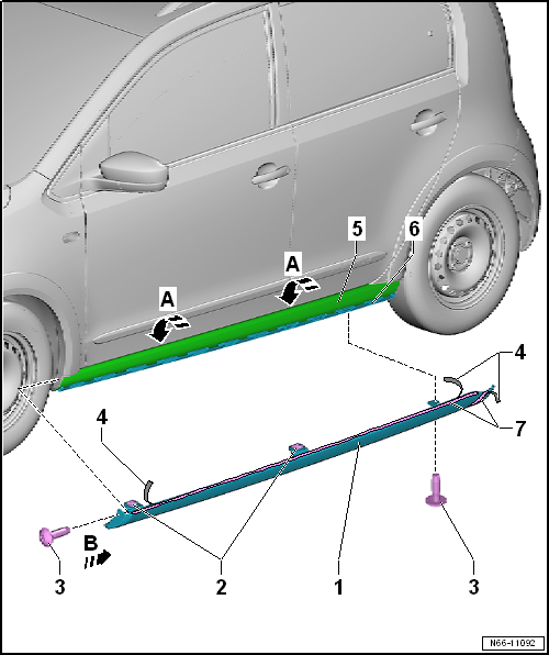
Assembly overview - rocker panel trim e-up!
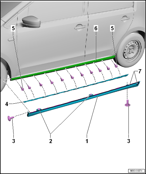
- Rocker panel trim
- Remove and install
- Clip
- 2 pieces
- Components of rocker panel trim
- Bolt
- 2 pieces
- 2 N·m
- Retaining strip
- Remove and install
- Bolt
- 11 pcs.
- 1,2 N·m
- Rocker panel
- Double-sided adhesive tape
- Components of rocker panel trim
Assembly overview - rocker panel trim Cross up!
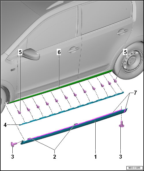
- Rocker panel trim
- Remove and install
- Clip
- 2 pieces
- Components of rocker panel trim
- Bolt
- 2 pieces
- 2 N·m
- Retaining strip
- Remove and install
- Bolt
- 11 pcs.
- 1,2 N·m
- Rocker panel
- Double-sided adhesive tape
- Components of rocker panel trim
Assembly overview - A-pillar trim
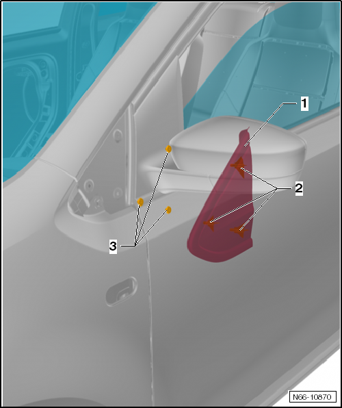
- A-pillar trim
- Expanding rivet
- Components of A-pillar trim
- Grommets
Removing and installing rocker panel trim
Removing and installing rocker panel trim e-up!
Installation notes
- The rocker panel trim cannot be removed without damage.
- Before removal, heat the rocker panel trim in the area of the adhesive surfaces with the hot air blower -V.A.G 1416-.
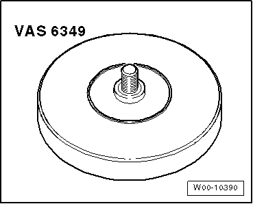
- If present, remove any adhesive residue from the adhesive tape with adhesive tape remover -VAS 6349-.
- When removing and installing rocker panel trim, use only adhesive remover -D 002 000 10- to remove adhesive residue.
- Make sure the adhesive surfaces are free of dust and grease.
- Glue the rocker panel trim on immediately after cleaning.
- Remove the protective film only immediately before installation.
- The processing temperature is approx. 21 °C.
Removing rocker panel trim
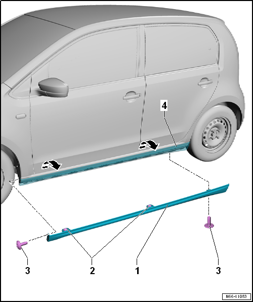
- Unscrew bolt -3-.
- Pry out expanding rivet -2-.
- Heat upper area of rocker panel extension -1- with the hot air blower -V.A.G 1416-.
- Pull rocker panel extension -1- upward out of retaining strip in direction of arrow B.
Removing retaining strip
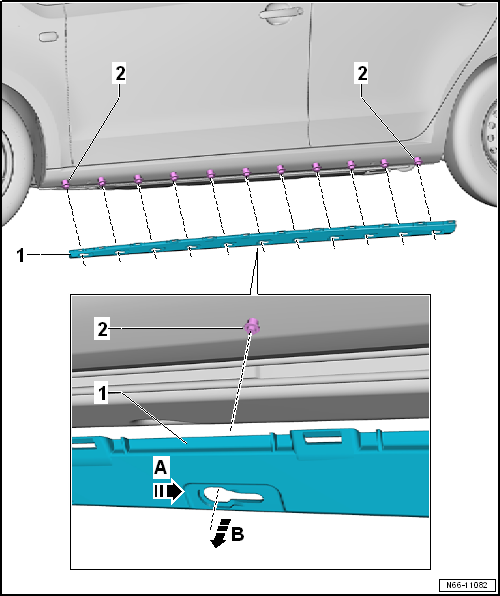
- Press retaining strip -1- firmly toward the rear in direction of arrow a.
- Lift retaining strip -1- evenly off all screws -2- in direction of arrow b.
Installing retaining strip

Note
- The screws for the retaining strip are corrosion-resistant, "silver" color. No further treatment is required.
- If a screw is overtightened, it must be replaced with a "black" oversize screw.
- There are no holes for the fastening screws.
- Measure the holes according to the table below.
- Center punch the holes for the fastening screws.
- Pre-drill the holes with a 1.5 mm drill bit.

Note
Dimension -a- is measured from the rear wheel arch.
Positions for the drilling screws of the retaining strip
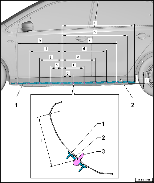
- 1007 mm ± 1 mm
- The dimension is measured from the rear edge of the rocker panel.
- 906 mm ± 1 mm
- 761 mm ± 1 mm
- 611 mm ± 1 mm
- 461 mm ± 1 mm
- 306 mm ± 1 mm
- 152 mm ± 1 mm
- 624 mm ± 1 mm
- 469 mm ± 1 mm
- 314 mm ± 1 mm
- 159 mm ± 1 mm
- 65 mm - 82 mm
- ascending from front to rear
- Screw in self-tapping screws -1- with cordless screwdriver -VAS 5036- at 2500 ± 500 rpm until the thread engages. Be sure to remove the cordless screwdriver -VAS 5036- now.
- Tighten the screws with the lowest torque 1.2 N·m - 0.1 N·m so that the screw is not overtightened.
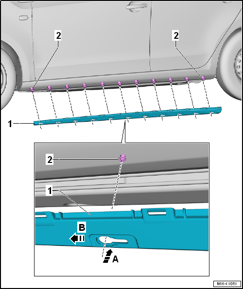
- All holes for the fastening screws -1- are present.
- Place retaining strip -1- onto screws -1- in direction of arrow a.
- Push retaining strip firmly toward the rear in direction of arrow b until it stops.
Installing rocker panel trim
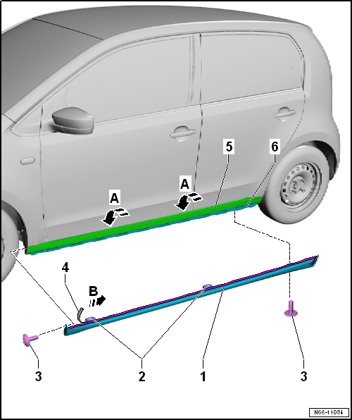
- Installation notes.
- Thoroughly clean rocker panel -5- in the area of the adhesive surface with the cleaning solution.
- Place rocker panel trim -1- onto retaining strip -6- and snap it in direction of arrow A.
- Align sill panel trim -1-.
- Tighten bolts -3-. Tightening torque.
- Insert expanding rivet -2-.
- Remove protective film -4- from the adhesive tape -arrow b-.
- Firmly press the sill panel trim against the sill in the area of the adhesive tape.
Removing and installing sill panel trim Cross up!
Installation notes
- The rocker panel trim cannot be removed without damage.
- Before removal, heat the rocker panel trim in the area of the adhesive surfaces with the hot air blower -V.A.G 1416-.
- If present, remove any adhesive residue from the adhesive tape with adhesive tape remover -VAS 6349-.
- When removing and installing rocker panel trim, use only adhesive remover -D 002 000 10- to remove adhesive residue.
- Make sure the adhesive surfaces are free of dust and grease.
- Glue the rocker panel trim on immediately after cleaning.
- Remove the protective film only immediately before installation.
- The processing temperature is approx. 21 °C.
Removing
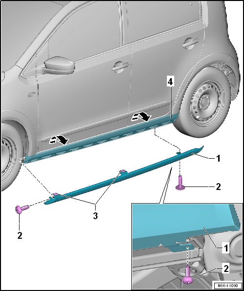
- Unscrew bolt -2-.
- Pry out expanding rivet -3-.
- Heat upper area of rocker panel extension -1- with the hot air blower -V.A.G 1416-.
- Pull sill extension -1- upward out of the retaining strip -arrows-.
Removing retaining strip
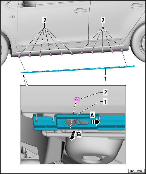
- Press retaining strip -1- firmly toward the rear in direction of arrow a.
- Lift retaining strip -1- evenly off all screws -2- in direction of arrow b.
Installing retaining strip

Note
- The screws for the retaining strip are corrosion-resistant, "silver" color. No further treatment is required.
- If a screw is overtightened, it must be replaced with a "black" oversize screw.
- There are no holes for the fastening screws.
- Measure the holes according to the table below.
- Center punch the holes for the fastening screws.
- Pre-drill the holes with a 1.5 mm drill bit.

Note
Dimension -a- is measured from the rear wheel arch.
Positions for the drilling screws of the retaining strip
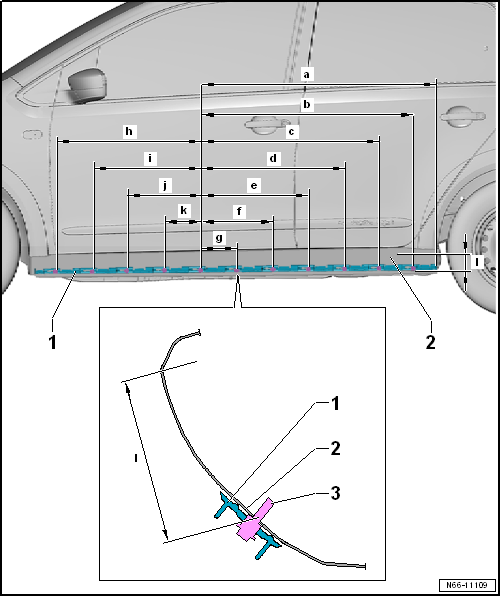
- 1007 mm ± 1 mm
- The dimension is measured from the rear edge of the rocker panel.
- 906 mm ± 1 mm
- 761 mm ± 1 mm
- 611 mm ± 1 mm
- 461 mm ± 1 mm
- 306 mm ± 1 mm
- 152 mm ± 1 mm
- 624 mm ± 1 mm
- 469 mm ± 1 mm
- 314 mm ± 1 mm
- 159 mm ± 1 mm
- 65 mm - 82 mm
- ascending from front to rear
- Screw in self-tapping screws -1- with cordless screwdriver -VAS 5036- at 2500 ± 500 rpm until the thread engages. Be sure to remove the cordless screwdriver -VAS 5036- now.
- Tighten the screws with the lowest torque 1.2 N·m - 0.1 N·m so that the screw is not overtightened.
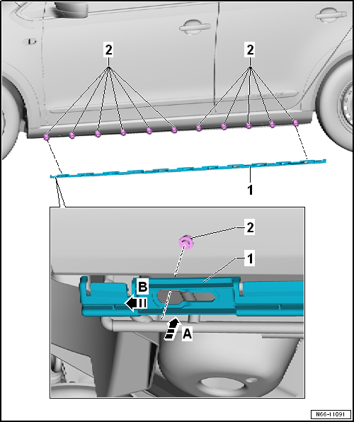
- All holes for the fastening screws -1- are present.
- Place retaining strip -1- onto screws -1- in direction of arrow a.
- Push retaining strip firmly toward the rear in direction of arrow b until it stops.
Installing
- Installation notes.
- Thoroughly clean rocker panel -5- in the area of the adhesive surface with the cleaning solution.
- Place rocker panel trim -1- onto retaining strip -6- and snap it in direction of arrow A.
- Align sill panel trim -1-.
- Tighten bolts -3-. Tightening torque.
- Insert expanding rivet -2-.
- Remove protective film -4- from the adhesive tape -arrow b-.
- Firmly press the sill panel trim against the sill in the area of the adhesive tape.
Removing and installing B-pillar trim

Note
The removal and installation procedure applies only to the left B-pillar trim. The procedure for the right B-pillar trim is similar.
Installation notes
- The bonded trim cannot be removed without damage.
- Before removal, heat the trim in the area of the bonded surfaces with heat gun -V.A.G 1416-.
- If present, remove any adhesive residue from the adhesive tape with adhesive tape remover -VAS 6349-.
- When removing and installing a trim, use only adhesive remover -D 002 000 10- to remove adhesive residue.
- Make sure the adhesive surfaces are free of dust and grease.
- Bond the trim immediately after cleaning.
- Remove the protective film only immediately before installation.
- The processing temperature is approx. 21 °C.
Removing
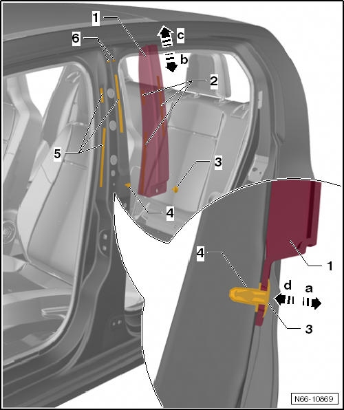
- Pull expanding rivet -3- out of grommet -4- -arrow a-.
- Observe installation notes.
- Pull B-pillar trim -1- downward -arrow direction b-.
- Peel B-pillar trim -1- off adhesive tapes -5-.
Installing
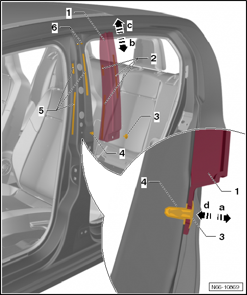
- Check grommets -4- and -6- for damage and replace if necessary.
- Observe installation notes.
- Clean bonded surfaces.
- Apply new adhesive tapes -5- and remove protective film.
- Slide B-pillar trim -1- into grommets -6- in direction c. Do not press onto the bonded surfaces yet.
- Slide expanding rivet -3- into grommet -4- -arrow d-.
- Firmly press B-pillar trim -1- in the area of adhesive tapes -5-.
Removing and installing wheel arch covers
Removing and installing front wheel arch covers
Installation notes
- The bonded trim cannot be removed without damage.
- Before removal, heat the trim in the area of the bonded surfaces with heat gun -V.A.G 1416-.
- If present, remove any adhesive residue from the adhesive tape with adhesive tape remover -VAS 6349-.
- When removing and installing a trim, use only adhesive remover -D 002 000 10- to remove adhesive residue.
- Make sure the adhesive surfaces are free of dust and grease.
- Bond the trim immediately after cleaning.
- Remove the protective film only immediately before installation.
- The processing temperature is approx. 21 °C.
Removing

Note
- The front wheel arch cover cannot be removed without damage.
- The removal and installation procedure applies only to the left side. The procedure for the right side is similar.
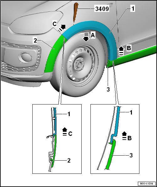
- Mask all adjacent painted surfaces.
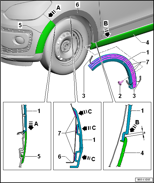
- Heat front wheel arch cover -1- with heat gun -V.A.G 1416-.
- Lift one corner of front wheel arch cover -1- with removal wedge -3409-.
- Reach under the corner and firmly pull front wheel arch cover -1- off the fender -arrow a-.
- Pull front wheel arch cover out from behind bumper trim -2- and sill panel trim -3- -arrows c and b-.
Installing
- Installation notes.
- Thread front wheel arch cover -1- into sill extension -4- and bumper trim -5- -arrows a and b-.
- Remove protective film -3- from front wheel arch cover -1- and firmly press onto the fender -arrows c-.
Removing and installing rear wheel arch covers
Installation notes
- The bonded cover cannot be removed without damage.
- Before removal, heat the cover in the area of the bonded surfaces with heat gun -V.A.G 1416-.
- If present, remove any adhesive residue from the adhesive tape with adhesive tape remover -VAS 6349-.
- When removing and installing a cover, use only adhesive remover -D 002 000 10- to remove adhesive residue.
- Make sure the adhesive surfaces are free of dust and grease.
- Bond the cover immediately after cleaning.
- Remove the protective film only immediately before installation.
- The processing temperature is approx. 21 °C.
Removing

Note
- The rear wheel arch cover cannot be removed without damage.
- The removal and installation procedure applies only to the left side. The procedure for the right side is similar.
- Mask all adjacent painted surfaces.
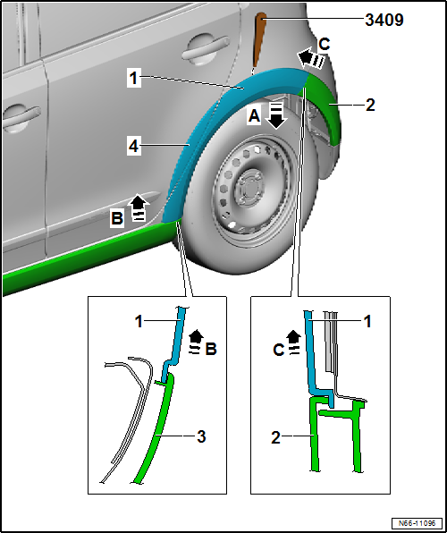
- Heat rear wheel arch cover -1- with heat gun -V.A.G 1416-.
- Lift one corner of rear wheel arch cover -1- with removal wedge -3409-.
- Reach under the corner and firmly pull rear wheel arch cover -1- off the fender.
- The same procedure applies to the cover on the door -4-.
Installing
- Installation notes.
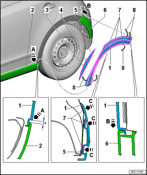
- Thread rear wheel arch cover -1- into sill panel trim -2- and bumper trim -6- -arrows a and b-.
- Align rear wheel arch cover -1- and remove protective film -8-.
- Firmly press rear wheel arch cover -1- against the side panel in the area of adhesive tapes -7- -arrow c-.
- The same procedure applies to the cover on the door -3-.
Removing and installing sill trims
Extra equipment Volkswagen R GmbH

Note
Depending on the model variant, either the "Black" sill trim or the "White" sill trim is fitted.
Required Special Tools, Test and Measuring Equipment and Auxiliary Items
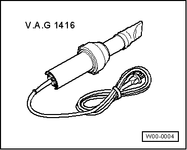
- Hot air blower -V.A.G 1416-
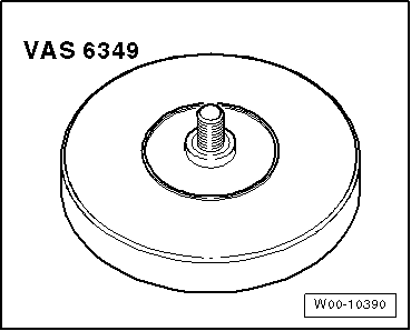
- Adhesive tape remover -VAS 6349-
Installation notes
- The bonded sill trims cannot be removed without damage.
- Before removal, heat the sill trim in the area of the bonded surfaces with heat gun -V.A.G 1416-.
- If present, remove any adhesive residue from the adhesive tape with adhesive tape remover -VAS 6349-.
- When removing and installing a sill trim, use only adhesive remover -D 002 000 10- to remove adhesive residue.
- Make sure the adhesive surfaces are free of dust and grease.
- Bond the sill trim immediately after cleaning.
- Remove the protective film only immediately before installation.
- The processing temperature is approx. 21 °C.
Front sill trim, 2-door

Note
The installation procedure applies to the left sill trim. The procedure for the right sill trim is similar.
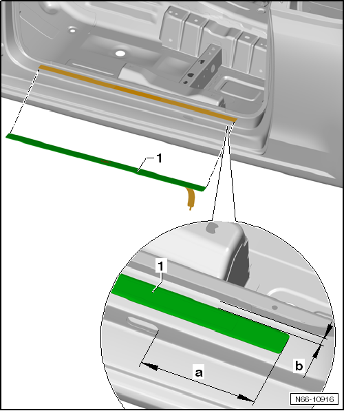
Removing
- Loosen door seal.
- Heat sill trim -1- with heat gun -V.A.G 1416- and peel it off the sill.
Installing
Observe installation notes
- Remove protective film from new sill trim -1-.
- Bond sill trim -1- to the sill at dimension a = 172.5 mm.
Distance between sill trim -1- and body flange, dimension b = 19 mm
Front sill trim, 4-door

Note
The installation procedure applies to the right sill trim. The procedure for the left sill trim is similar.
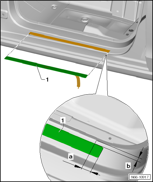
Removing
- Loosen door seal.
- Heat sill trim -1- with heat gun -V.A.G 1416- and peel it off the sill.
Installing
Observe installation notes
- Remove protective film from new sill trim -1-.
- Bond sill trim -1- to the sill at dimension a = 38.5 mm.
Distance between sill trim -1- and body flange, dimension b = 19 mm
Removing and installing protective strips
Extra equipment Volkswagen R GmbH
Required Special Tools, Test and Measuring Equipment and Auxiliary Items
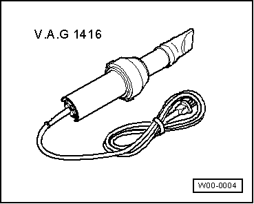
- Heat gun -V.A.G 1416-.
- Adhesive tape remover -VAS 6349-.
Installation notes
- The bonded protective strips cannot be removed without damage.
- Before removal, heat the protective strips in the area of the bonded surfaces with heat gun -V.A.G 1416-.
- If present, remove any adhesive residue from the adhesive tape with adhesive tape remover -VAS 6349-.
- When removing and installing a protective strip, use only adhesive remover -D 002 000 10- to remove adhesive residue.
- Make sure the adhesive surfaces are free of dust and grease.
- Bond the protective strips immediately after cleaning.
- Remove the protective film only immediately before installation.
- The processing temperature is approx. 21 °C.

Note
The installation procedure applies to the left side. For the right side, the procedure is similar.
Removing
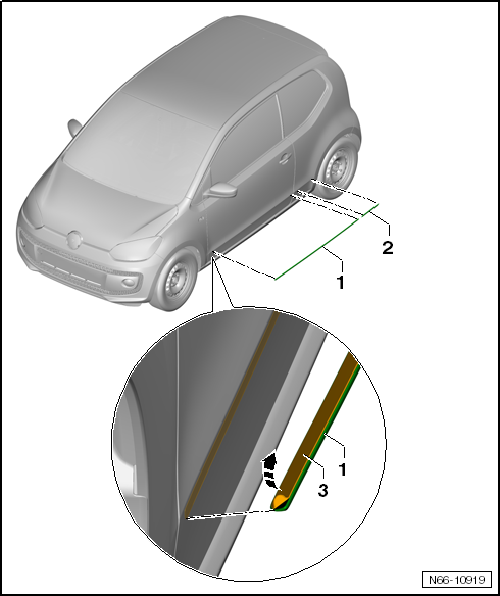
- Heat door protective strip -1- or side panel protective strip -2- with heat gun -V.A.G 1416- and peel it off.
Installing
Observe installation notes.
- Remove protective film -3- from new door protective strip -1- or side panel protective strip -2-.
- Place protective strips onto the door or side panel edge and press firmly.