Steering column switch module
Removing and installing steering column switch module
Required Special Tools, Test and Measuring Equipment and Auxiliary Items
- Torque Wrench -V.A.G 1331-

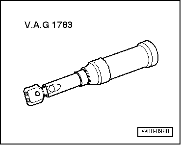
- Torque wrench -V.A.G 1783-
General description
Depending on equipment, the following components are integrated in the combination switch:
- Turn signal switch -E2-
- Switch for windshield washer pump (automatic wiper/washer function and headlight washer system) -E44-
- Switch for manual dimming and headlight flasher -E4-
- Switch for parking light -E19-
- Windshield wiper switch for intermittent operation -E22-
- Switch for rear window wiper -E34-
- Regulator for windshield wiper intermittent operation -E38-
- Cruise control switch -E45-
- SET button for cruise control -E227-

Note
If any of the components listed above is defective, the complete combination switch must be replaced.
The clockspring for airbag and return ring with slip ring -F138- is secured to the combination switch with a detachable connection and must be replaced separately → Body interior assembly work.
Fault recognition and fault indication
The following components are capable of self-diagnosis:
- Turn signal switch -E2-
- Switch for windshield washer pump (automatic wiper/washer function and headlight washer system) -E44-
- Cruise control switch -E45-
- Windshield wiper switch for intermittent operation -E22-
- Steering angle sensor -G85-

Note
- When removing and installing the clockspring for airbag and return ring with slip ring -F138- or the combination switch, the steering wheel must be in the "center position" (wheels in the "straight-ahead position").
- The clockspring for airbag and return ring with slip ring -F138- must not be turned out of its position.
- If the steering angle sensor -G85- is integrated in the clockspring for airbag and return ring with slip ring -F138- (vehicles with EPS = electric power steering and ESP), the basic setting of the steering angle sensor must be carried out after installation work on the combination switch.
- If the steering angle sensor -G85- is integrated in the clockspring for airbag and return ring with slip ring -F138-, there is a yellow marking for the center position.
Removing
- Disconnect battery.
- Turn the steering wheel to the "center position" (wheels in the "straight-ahead position").
- Remove the steering wheel → Chassis, axles, steering.
- Move the steering column to the lowest position using the steering column adjustment and lock it with the locking lever.
- Remove the steering column cover → Body interior assembly work.
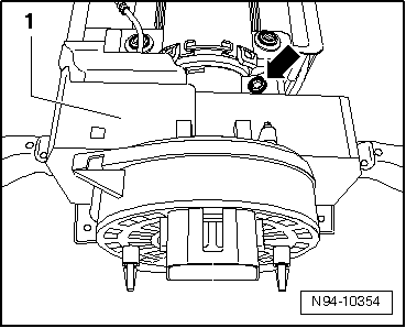
- Loosen the mounting screw -arrow- of combination switch -1-.
- Pull locking tab -2- up in -arrow direction B- and disconnect connector -1- from combination switch -3-.
- Pull combination switch -3- off the steering column toward the rear.
Installing
Installation is carried out in the reverse order of removal, observing the following:
- If the clockspring was accidentally turned out of the center position, carefully turn it from stop to stop while counting the turns to determine the center position again.
- If the steering angle sensor -G85- is integrated in the clockspring for airbag and return ring with slip ring -F138- (vehicles with EPS = electric power steering and ESP), carry out the basic setting of the steering angle sensor.

Removing and installing clockspring for airbag and return ring with slip ring -F138-
Removing
- Disconnect battery.
- Turn the steering wheel to the "center position" (wheels in the "straight-ahead position").
- Remove the steering wheel → Chassis, axles, steering.
- Move the steering column to the lowest position using the steering column adjustment and lock it with the locking lever.
- Remove the steering column cover → Body interior assembly work.
Removing and installing steering angle sensor -G85-

Note
The steering angle sensor is installed depending on equipment.
The steering angle sensor -G85- is integrated in the clockspring and forms one component.
- Remove steering angle sensor -G85-, see Removing and installing clockspring for airbag and return ring with slip ring -F138-
Removing and installing ignition starter switch
Removing
- Disconnect battery.
- Remove combination switch -E595-.
- Pull primary lock -2-, unlock connector -1- and disconnect it from ignition starter switch -D-.

- Remove the locking varnish from the two clamping screws -2-.
- Loosen the two clamping screws -2- slightly and pull ignition starter switch -D--1- out of the steering lock housing in -arrow direction-.
Installing
- Push the ignition starter switch into the steering lock housing.

Note
When installing the ignition starter switch, make sure that the ignition starter switch and the lock cylinder are in the same position, e.g. "ignition on".
- Tighten the clamping screws and seal them with locking varnish.
- Connect the connector to the ignition starter switch and push in the primary lock.
- Install all components in the reverse order of removal.

Checking ignition starter switch
- Connect the vehicle diagnostic tester.
- In the vehicle diagnostic tester, select the operating mode "Guided Fault Finding".
- Using the "Jump" button, select "Function/component selection" and then the following menu items in sequence:
- Body
- Electrical system
- Systems capable of self-diagnosis
- Electrical system control module J519
- Electrical components
- Ignition starter switch
Removing and installing lock cylinder
Removing
- Disconnect battery.
- Remove the steering wheel → Chassis, axles, steering.
- Remove the steering column cover → Body interior assembly work.
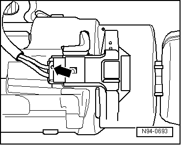
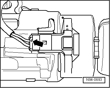
- Unlock and disconnect connector -arrow- of immobilizer reading coil -D2- on the lock cylinder.

Note
Immobilizer reading coil -D2- is attached to the lock cylinder and cannot be replaced separately.
- Insert the ignition key into the lock cylinder and turn it to position "Drive".
Key positions of the lock cylinder:
- Position "Stop"
- Position "Drive"
- Position "Start"

Note

For clarity, the following illustration shows a removed lock cylinder without the ignition key.
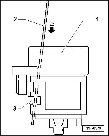
- Insert a steel wire (approx. Ø 1.2 mm) into the hole -arrow- next to the ignition key.
- Use steel wire -2- to unlock locking lever -3- of lock cylinder -1- -arrow-.
- Pull lock cylinder -1- out of the steering lock housing.
Installing

Note
For clarity, the ignition key is not shown in the following illustration.
- Insert the ignition key into the lock cylinder and turn it to position "Drive".
- Use steel wire -2- to unlock locking lever -3- of lock cylinder -1- -arrow-.
- Insert lock cylinder -1- into the steering lock housing.

Note
The connector for the immobilizer reader coil must be inserted into the guide on the steering lock housing.
- Pull the steel wire -2- out of the lock cylinder -1- and check that the lock cylinder is firmly seated in the steering lock housing.
- Plug the connector -arrow- onto the immobilizer reader coil -D2- on the lock cylinder.
- Install all components in the reverse order of removal.
Removing and installing steering lock housing

Caution!
When disconnecting and connecting the battery, follow the procedure described in the repair manual.

Caution!
- The steering lock can be damaged.
- If the steering lock is operated without the lock cylinder, it will lock and must be replaced.
- Do not operate the steering lock without the lock cylinder.
Required Special Tools, Test and Measuring Equipment and Auxiliary Items
- Angle hand drill
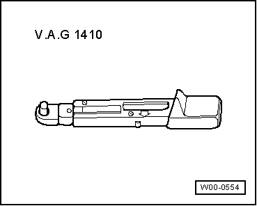
- Torque wrench -V.A.G 1410-
Removing

Note
To remove the steering lock housing, the break-off bolts must be drilled out. New break-off bolts are required for installation → ETKA (Electronic Parts Catalog).
- Disconnect battery.
- Remove the instrument cluster insert.
- Remove the combination switch on the steering column.
- Remove the lock cylinder.
- Remove the ignition starter switch.

Caution!
- Before drilling out the break-off bolts, it is essential to first remove all components attached to the steering lock housing.
- Drilling out can allow metal shavings to get into adjacent components, which can cause damage and/or malfunctions!

WARNING!
Risk of eye injury from metal shavings.
Metal shavings can fly off while drilling and cause eye injuries.
Wear safety goggles.
- Unscrew the mounting bolt -1- and remove the wire.
- Drill out the break-off bolts -arrows- of the steering lock housing -2-.

Note
Bolts M8 -arrows-, core hole diameter 6.8 mm.
- Pull the steering lock housing -2- off the steering column towards the rear.

Installing
- Slide the steering lock housing -2- straight onto the steering column until it stops, and align it with the threaded holes.
- Bolt the steering lock housing -2- to the steering column using new break-off bolts -arrows-.
- Tighten the new break-off bolts -arrows- until the bolt heads break off.
- Secure the wire with the mounting bolt -1-.
- Install all components in the reverse order of removal.
