Overhaul - Crankshaft Inspection
PROCEDURE
1. Carefully inspect the crankshaft for damage and take precise measurements of the main and connecting rod journals. Main and connecting rod journals can be ground up to three times, so the crankshaft can be fitted with undersize bearing shells. The connecting rod journal diameter is the same for all engine types.
2. Clamp the crankshaft between the centers of a lathe (or place the main bearing journals in V-blocks) and use a dial indicator to measure runout at the center journal. Runout must not exceed 0.06 mm. Otherwise, replace the crankshaft.
3. Measure the main bearing and connecting rod bearing clearances.
4. Thoroughly clean the bearing shells and place them in the main bearing seats of the cylinder block or in the connecting rods.
5. Place a piece of Plastigage on each main bearing journal and on each main bearing cap with bearing shells installed. Tighten the bolts to 65 N·m. Do not rotate the crankshaft.
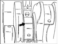
6. To check connecting rod bearing clearances, position the connecting rod on the connecting rod journal and place a piece of Plastigage on the upper part of the connecting rod journal (arrow). Install the bearing cap with shell and tighten the nuts to 30 N·m. Since the crankshaft must not be rotated, measurements are made on the two connecting rod bearings located at bottom dead center (BDC).
7. Remove the main bearing caps. For connecting rod bearings, remove both caps one at a time.
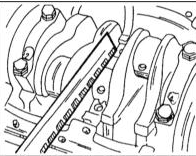
8. Using the scale included with the Plastigage set, measure the crushed strip at its widest point. If this value exceeds 0.17 mm for main bearings, replace the bearing caps with new ones. Take into account whether the journals have been ground previously.
9. To check the clearances of the remaining bearings, inspect the crankshaft and measure the other two connecting rod bearings. If you do not have a Plastigage set but have a dial bore gauge, you can measure the main and connecting rod bearing clearances using the method described below.
10. Install the bearing caps with shells according to the bearing numbers on the cylinder block and tighten the bolts to 65 N·m. Be sure to pay attention
CAUTION
to ensure the bearing shells return to their original positions. If connecting rod bearing clearances are being measured, install the shells in the connecting rods and caps and secure the caps with the original nuts, tightening them to 30 N·m.
11. Measure the inside diameters of the bearings. Observe the measurement directions A and B and measurement points 1 and 2.
2. This allows determination of out-of-round (A and B) and taper (1 and 2). Record the results for each bearing.

12. Measure the diameters of all journals in turn using a micrometer. Again, take measurements at the specific points indicated by the arrows. Record the measurement results for all journals.
13. Subtract the journal diameter measurements from the bearing inside diameter measurements. The result is the bearing clearance (main or connecting rod) and must correspond to the value specified in the Specifications.
Test yourself
A quick Audi A3 quiz: every answer comes with an explanation and a link to the manual page.