Removing and Installing the Engine/Manual Transmission
GENERAL INFORMATION
Engine 1.8 L
The engine and transmission are removed downward. An engine crane is required to remove the engine/transmission unit. Never remove the engine/transmission unit using a shop lift, as this may cause severe engine damage.
Since several connections on the underside of the vehicle must be loosened, four support stands are required, and a lift is needed to raise the vehicle. Before installing the engine, the fenders in the engine compartment must be protected with covers.
Depending on the model year and equipment of the vehicle, electrical wires, vacuum hoses and cooling system hoses may be routed differently. Since it is not possible to describe the routing of all variants here, it is recommended to label the relevant lines before disconnecting them.
Required special tools and auxiliary materials:
– Engine crane – Spring clamp pliers, e.g. HAZET 798–5 – Lifting bracket, e.g. AUDI 2024 A – MoS2 grease, e.g. AUDI G 000 100 – Torque wrench 5…50 N•m – Torque wrench 40…200 N•m – Cable connector REMOVAL
CAUTION
Cable connectors that are removed or cut during engine removal must be reinstalled in their original positions. Mark their installation locations for this purpose. To disconnect connections, press in the locks and pull on the plug.PROCEDURE
1. Disconnect the negative (–) battery cable with the ignition switched off.
CAUTION
As a result, information is erased from the electronic memory units, such as the radio code. Without the code, the radio can only be activated by the manufacturer or an AUDI service station. Therefore, observe the instructions in the subsection Entering the radio code.2. Remove the battery. Refer to the subsection Removing and installing battery.
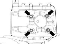
3. Unscrew the mounting bolts and remove the battery bracket.
4. Remove the starter motor. Refer to the subsection Testing, removing and installing starter solenoid.
5. Remove the air filter housing. Refer to the subsection Removing and installing air filter housing.
6. Unscrew the mounting bolts and remove the air duct to the air filter on the bumper.
7. Remove the engine compartment undertray. Refer to the subsection Removing and installing engine compartment undertray.
8. Remove the right drive shaft. Refer to the subsection Removing and installing drive shafts.
9. Disconnect the left drive shaft from the transmission flange and secure it with wire to the stabilizer bar or the underbody.
10. Drain the coolant. Refer to the subsection Changing coolant.
11. Engine 150 L kW: Remove the connecting pipes between the turbocharger/charge air cooler, turbocharger/air filter and charge air cooler/intake manifold. To do this, remove the clamps from the hoses.
12. Loosen the tension of the V-ribbed belt and remove it. Refer to the subsections Removing and installing V-ribbed belt and Removing and installing V-belt.
13. Unscrew the mounting bolts and remove the power steering pump from the bracket. Secure it with wire to the body. Do not disconnect the hoses.
CAUTION
Do not kink the hoses. If the system was opened during removal, the air must be bled from it. Refer to the subsection Removing and installing power steering pump.Vehicles with air conditioning:
CAUTION
Do not open the air conditioning refrigerant circuit. Contact of refrigerant with skin can cause frostbite. Loosen the clamps securing the air conditioning cooling system. Do not twist, pinch or bend the air conditioning lines and hoses.
14. Unscrew the compressor mounting bolts (A) and (B) and secure the compressor with wire to the hood latch so that the hoses are not stretched.
15. Remove the exhaust front pipe and catalytic converter. Refer to the subsection Removing and installing exhaust system.
16. Disconnect the accelerator cable. Do not remove the stop. Refer to the subsection Adjusting accelerator linkage.
17. Remove the engine cover from the intake manifold.
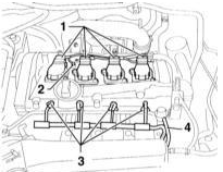
18. Disconnect the plug connectors of the ignition coils –1– and injectors –3–. Disconnect the negative cable –2–. The illustration shows the engine 150 L kW.
19. Disconnect the vacuum line –4– at the fuel pressure regulator.
20. Disconnect the vacuum and intake hoses at the engine and turbocharger (engines 150 and 180 L kW). If necessary, mark the hoses and connectors to avoid mistakes during assembly.
21. Disconnect all plug connectors between the engine and transmission and the body.
CAUTION
The fuel system is under pressure! Before opening hose connections, cover them with a thick cloth. Then carefully release the pressure. Wear protective goggles. Risk of spray injury!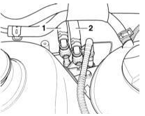
22. Disconnect the fuel supply line –1– and return line –2– at the fuel distributor by pressing the release buttons on the coupling. Mark the hoses with tape to simplify reassembly.
23. Close the fuel lines with plastic film and rubber caps to prevent dirt from entering the system.
24. Disconnect the 2 coolant hoses from the heater heat exchanger at the front bulkhead of the engine compartment by opening the clamps.
25. Remove all coolant hoses from the engine to the upper section and to the expansion tank by opening the clamps and removing the hoses.
26. Remove the fan with the bracket. Refer to Radiator and Fan Removal and Installation.
27. Vehicles with MT: Remove the shift linkages and the clutch slave cylinder.
CAUTION
After removing the clutch slave cylinder, do not depress the clutch pedal.28. Vehicles with AT: Remove the bolts and the power steering pressure hose bracket from the transmission mount. Disconnect the selector cable at the transmission. Refer to Automatic Transmission Selector Cable Adjustment.
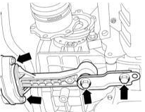
29. Remove the bolts securing the pendulum mount at the bottom between the body and the engine/transmission unit.
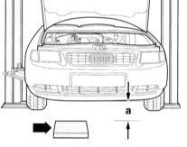
30. Raise the vehicle. The vehicle must be at least a = 60 mm above the ground.
31. Place a wooden block (arrow) measuring 40 x 30 cm and 15 cm thick on the ground to support the engine in the area of the oil pan.

32. Connect the AUDI-2024A lifting device with hook 3180 to the lifting eyes on the engine. Connect the vertical perforated bars to holes 1 and 5 of the cross bar. Insert a pin from the flywheel side into the second hole of the bar, and from the pulley side into the third hole. Holes are counted from the hook side.
CAUTION
Use locking pins on hooks and locating pins. To match the center of gravity of the assembly, the perforated bars must be correctly adjusted to length.33. If the appropriate lifting device is not available, a chain may be used to lift the unit.
34. Raise the engine/transmission unit with a crane so that the engine mounts are unloaded.
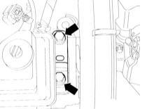
35. Remove the upper right engine/transmission mount.
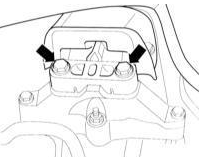
36. Remove the bolts securing the left transmission mount.
37. Make sure all hoses and lines running from the engine and transmission to the chassis are disconnected.
38. Pull the engine/transmission unit forward as far as possible and slowly lower it onto the wooden spacer. Perform this operation carefully to avoid damaging components.
CAUTION
Secure the unit so that it cannot tip over.39. If necessary, separate the transmission from the engine. Refer to Manual Transmission Removal and Installation. INSTALLATION
40. Check the engine mounts and the coolant, oil and fuel hoses for pores and cracks. Replace if necessary.
41. Only if the engine was separated from the transmission: Check the clutch. Insert the engine/transmission bolts and tighten them to the specified torque. Follow the instructions in Manual Transmission Removal and Installation.
42. Install the engine/transmission unit in place and secure it hand-tight with new bolts.
43. Secure the pendulum arm hand-tight with new bolts.
44. Align the engine/transmission unit by rocking it firmly by hand.
45. Tighten the engine/transmission mounts and the pendulum arm to the torques specified in the Specifications. First tighten all bolts with a torque wrench, then turn the bolts an additional 90° (1/4 turn) with a standard wrench.
CAUTION
Bolts are permanently stretched when tightened. Therefore, always replace bolts after each tightening. Before tightening, measure the bolt thread diameter, as this determines the tightening torque.46. If the A/C compressor was removed, secure it with a torque of 45 N·m.
47. Install the power steering pump. Refer to Power Steering Pump Removal and Installation.
48. Install the starter motor. Refer to Starter Motor Removal and Installation.
49. Install and tension the drive belt. Refer to Ribbed V-Belt Removal and Installation and V-Belt Removal and Installation.
50. Secure the air duct to the air filter at the clip bracket.
51. Install the air filter housing. Refer to Air Filter Housing Removal and Installation.
52. Engine 150 L hp: Install the connecting pipes between the turbocharger and the charge air cooler, the turbocharger and the air filter, and the charge air cooler and the intake manifold. Secure the hoses with clamps.
53. Install the exhaust pipe/catalytic converter with new gaskets. Refer to Exhaust System Removal and Installation.
54. Install the left and right drive shafts. Refer to Drive Shaft Removal and Installation.
55. Connect the throttle linkage and adjust it. Refer to Throttle Linkage Adjustment.
56. Connect the supply and return fuel lines to the fuel rail. The quick-connect couplings must click audibly into place.
57. Connect the heater hoses running to and from the heat exchanger at the front bulkhead of the engine compartment. Secure them with clamps.
58. Install the radiator fan with the bracket. Refer to Radiator and Fan Removal and Installation.
59. Vehicles with MT: Install the shift linkages in place and adjust them. Refer to Shift Linkage.
60. Install the clutch slave cylinder on the manual transmission. Refer to Clutch Removal, Installation and Inspection.
61. Vehicles with AT: Secure the power steering pressure hose bracket to the transmission mount. Install the selector rod on the transmission and adjust it. Refer to Clutch Removal, Installation and Inspection.
62. Connect the electrical wires according to the markings made during removal, and secure them.
63. Secure the electrical wires at their original mounting points. Fasten them with clamps.
64. Install and secure the battery holder in place.
65. Install the battery without connecting the negative cable yet. Refer to Battery Removal and Installation.
66. Make sure the electrical wires, vacuum hoses, coolant hoses and fuel hoses are connected according to their markings.
67. Check the engine and transmission oil levels. Add oil if necessary.
68. Check the coolant antifreeze content and top up if necessary. Refer to Coolant Replacement and Fluid Level Checks, Leak Inspection.
69. Install the engine cover on the intake manifold.
70. Install the engine compartment undercover. Refer to Engine Compartment Undercover Removal and Installation.
71. Connect the negative (–) battery cable.
CAUTION
Activate the automatic high-position function of the electric window regulator, and set the clock and enter the radio code. Refer to the subsection Entering the radio code.72. Start the engine and warm it up to operating temperature. Check the oil and coolant levels. Check all hose connections for leaks.
73. Check the headlight aim. Refer to Headlight Aiming.
CAUTION
When disconnecting various electrical connectors, fault codes are stored in the control units; these must be erased after installation. This requires an electronic tester connected to the vehicle diagnostic connector. For this purpose, contact an AUDI service station.Test yourself
A quick Audi A3 quiz: every answer comes with an explanation and a link to the manual page.