Brake Disc/Caliper Removal and Installation
GENERAL INFORMATION
Corroded brake discs cause a vibration effect during braking that does not disappear with longer braking. In this case the brake discs must be replaced. REMOVAL
PROCEDURE
1. Mark the position of the wheels relative to the hub with paint. This allows the balanced wheel to be installed in its original position. Loosen the wheel bolts while the vehicle is still on the ground. Raise the vehicle and place it on stands. Remove the wheels.
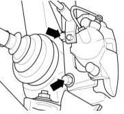
2. Front brake with FN-3 caliper: Remove the 2 mounting bolts (indicated by arrows) and remove the caliper from the guide pin and brake disc. For the FN-3 caliper, refer to the illustration Rear Wheel Disc Brake Assembly in the Rear Disc Brake Caliper Removal and Installation subsection.
3. Front brake with FN-III caliper: Remove the brake pads, refer to the Front Brake Pad Replacement subsection.
4. Rear wheel brakes: Remove the 2 caliper mounting bolts from the axle beam and remove the caliper from the brake disc, refer to the illustration Rear Wheel Disc Brake Assembly in the Rear Disc Brake Caliper Removal and Installation subsection.
5. Secure the caliper to the suspension with a wire hook so that the brake hose is not stretched.
CAUTION
Do not disconnect the brake hose; otherwise, air must be bled from the brake system after installation.6. If the caliper must be removed completely:
- On the front caliper, disconnect the brake line at the union. - On the rear caliper, first disconnect the brake line at the connection to the hose. Then, if necessary, disconnect the hose from the caliper. Additionally, disconnect the parking brake cable.
CAUTION
When the brake circuit is opened, brake fluid will leak out. Collect the fluid in a container intended for this purpose. The fluid can also be pumped out of the reservoir beforehand.7. Remove the Phillips-head screw securing the brake disc.
8. Remove the brake disc.
CAUTION
Do not remove the brake disc from the hub by applying force (hammer blows). Use a rust penetrating agent for this purpose. If the disc can only be removed by hammer blows, for safety reasons the brake discs and wheel bearings must be replaced. Bearing replacement must be carried out at a workshop, as only there is a suitable press normally available. After using a puller, the brake discs must also be replaced.INSTALLATION
To ensure even braking on both sides, both brake discs must have the same surface roughness. Therefore, both brake discs must always be replaced. At a workshop, the disc runout can be checked. Maximum disc surface runout: 0.05 mm; maximum permissible difference in disc thickness: 0.01 mm.
PROCEDURE
1. Measure the brake disc thickness, refer to the appropriate section.
2. If present, remove rust from the brake disc flange and hub.
3. Clean the new disc with thinner to remove the protective coating.
4. Install the new brake discs on the hub and secure with Phillips-head screws.
5. Front wheel brakes with FS-III caliper: Install the brake pads, refer to the Front Brake Pad Replacement subsection.
6. Front wheel brakes with FS-3 caliper: Install the caliper with the brake pads. Make sure the brake hose is not twisted or stretched. Tighten the caliper to 125 N·m.
CAUTION
If the old ribbed bolts are reused, clean the ribs thoroughly with a wire brush beforehand.7. Rear wheel brakes: Tighten to 65 N·m. Connect the parking brake cable.
CAUTION
If the brake hose was removed, install it and bleed the brake system, refer to Bleeding the Brake System.8. Install the wheels so that the marks made during removal are aligned. Apply a thin layer of bearing grease to the wheel centering collar on the hub beforehand. Install the wheel bolts. Lower the vehicle onto the wheels and tighten the bolts in a crisscross pattern to 120 N·m.
CAUTION
Depress the brake pedal several times firmly until a distinct pedal resistance is felt. This seats the brake pads against the brake disc.9. Check the brake fluid level in the reservoir. Top up if necessary.
10. Rear wheel brakes: Adjust the parking brake, refer to the Parking Brake Adjustment subsection.
CAUTION
Check the following for security:– Are the brake hose connections securely tightened? – Is the brake hose secured in its bracket? – Are the bleed screws tightened? – Is there sufficient brake fluid in the reservoir? – With the engine running, check the system for leaks. Press the brake pedal with a force of 200 – 300 N (20 – 30 kg) for 10 s. The pedal must not move away. Check all connections for leaks.
11. Carefully bed in the new brake pads. To do this, brake the vehicle several times from 80 to 40 km/h, applying the pedal lightly. Allow the brakes to cool between applications.
Test yourself
A quick Audi A3 quiz: every answer comes with an explanation and a link to the manual page.