Cylinder Head - Removal and Installation
Models 520i, 523i, 528i (M52 engine)
Signs of cylinder head gasket damage include:
a) Loss of power.
b) Coolant leaks. White smoke from the exhaust when the engine is warm.
c) Oil leaks.
d) Coolant in the engine oil. Oil level does not drop but rises. Gray color of engine oil, foam on the oil level indicator, reduced oil viscosity.
e) Engine oil in the coolant.
* In this case, after repair, remove the radiator and flush it with BMW special cleaner to remove oil residue from the radiator.
f) Foaming of coolant.
g) No compression in two adjacent cylinders.
Removal
The cylinder head is removed only after the engine has cooled down. The intake manifold and exhaust manifold are not disconnected.
* Some procedures are described in more detail in Engine - Removal and Installation. It is recommended to review that section in detail.
REMOVAL
1. Disconnect the negative cable from the battery. The battery is located in the trunk behind the right side trim.
* Disconnecting the battery erases data in electronic control modules, such as engine fault memory. Refer to Battery - Removal and Installation.
2. Raise and support the vehicle on stands.
3. Unscrew the mounting bolts and remove the tailpipe from the exhaust manifold. Refer to Exhaust System - Removal and Installation.
4. Drain the coolant. Refer to Coolant - Replacement. Check coolant antifreeze protection. Visually inspect the cooling system.
5. Drain the coolant from the engine. To do so, remove the plug on the side of the cylinder block below the exhaust manifold. After draining, immediately reinstall and tighten the plug.
6. Remove the spark plugs. Refer to Spark Plugs - Inspection and Replacement.
7. Remove the intake manifold. Refer to Intake Manifold - Removal and Installation.
8. Disconnect the electrical connector. Press in the wire lock. Refer to the accompanying illustration.
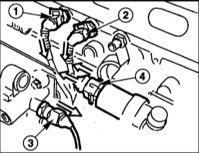
1 — coolant temperature sensor
2 — remote thermometer
3 — oil pressure indicator sensor
4 — idle speed control valve
9. Remove the cylinder head cover mounting bolts and remove the cylinder head cover. Note the position of the rubber spacers so that they can be installed in their original locations during installation. Refer to the accompanying illustration.

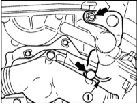
10. Disconnect the cable duct from the thermostat housing. To do so, open the clips on the side. Refer to the accompanying illustration.

11. Remove the intake camshaft cover. Refer to the accompanying illustration.

12. Disconnect the engine lifting brackets. Note the position of cable (1) for installation. Refer to the accompanying illustration.
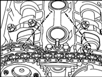
13. Position the No. 1 cylinder piston at TDC. The intake and exhaust camshaft lobes of the No. 1 cylinder must face up. Rotate the engine as follows:
a) Engage 5th gear and move the vehicle on a level surface.
b) Using a socket on the central crankshaft pulley bolt, turn the crankshaft in the direction of rotation (manual transmission in neutral).
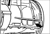
14. Lock the crankshaft at TDC using tool 11 2 300 or a suitable pin. To do so, insert the pin through the hole in the cylinder block into the hole in the flywheel after removing the plug. Refer to the accompanying illustration.
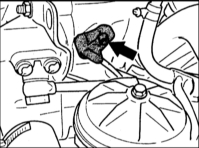
15. Disconnect the oil line from the VANOS actuating element and close the opening with a clean plug. Refer to the accompanying illustration.

16. Disconnect the plug connector from the VANOS actuating element solenoid valve.
17. Unscrew the stud. Refer to the accompanying illustration.
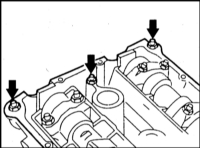
18. Secure the camshafts at TDC of the No. 1 cylinder piston using the tool shown in the illustration. If necessary, the camshafts can be turned using a 24 mm hex. Refer to the accompanying illustration.
* Do not damage the camshaft housings. If necessary, grind down the flats of the wrench to make it thinner.
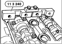
19. If the camshaft turns so that the valves of cylinders 1 and 6 start to move, turn the crankshaft 30° from TDC in the direction of engine rotation, and only then turn the camshaft. This prevents the valves from contacting the pistons. Refer to the accompanying illustration.
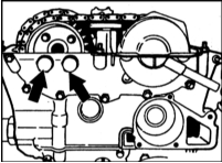
20. Remove the plugs from the actuating element.
21. Loosen the bolts on the exhaust camshaft sprocket. Refer to the accompanying illustration.
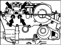
22. Press down the upper chain tensioner and secure it in this position by inserting the appropriate BMW tool. Refer to the accompanying illustration.
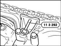
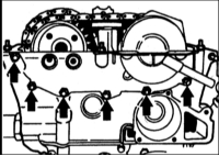
23. Remove the nuts and the cover. Refer to the accompanying illustration.
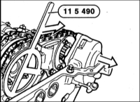
24. Remove the VANOS actuating element and turn the sprockets fully clockwise. If the sprockets cannot be turned by hand, the disc spring is the cause. In this case, use the special BMW tool as shown in the illustration. Refer to the accompanying illustration.
25. Disconnect the cylinder identification sensor. Disconnect the sensor plug connector. Refer to the accompanying illustration.
26. Remove the mounting bolts from the intake camshaft sprocket. Remove the thrust washer from the sprocket. Refer to the accompanying illustration.
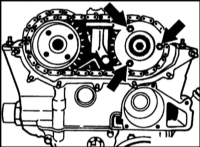
27. Remove both sprockets with the chain from the camshafts.
28. Disconnect the upper chain tensioner bracket. Refer to the accompanying illustration.

29. Unscrew the tensioner from the cylinder head.
* Hold the tensioner, as it is pressed by spring force. Refer to the accompanying illustration.
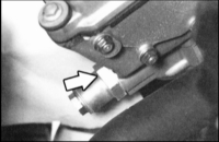
30. Remove the chain guide. Then remove the exhaust camshaft sprocket.
* Secure the chain with wire to prevent it from slipping down. Refer to the accompanying illustration.
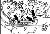
31. Remove the two bolts (arrows in the accompanying illustration).
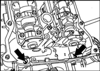
32. Loosen the cylinder head bolts in several stages, working from the outside in. A Torx wrench, such as HAZET 2925 or BMW 11 2 250, is required.
* Do not place the removed cylinder head on the sealing surface. The fully open valves may be damaged. Place the cylinder head on two wooden blocks.
INSTALLATION
1. Remove sealant residue using solvent and a hardwood scraper. Make sure sealant residue does not enter the holes. Cover the holes with rags.
2. Thoroughly blow out the cylinder head bolt holes with compressed air to remove oil and sealant residue, or clean them with a rag wrapped around a screwdriver.
* Oil must not accumulate in blind holes, as this may affect correct torque readings of the bolts. It may also cause the cylinder block to crack.
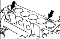
3. Check the locating sleeves for damage and correct seating. They are used to center the cylinder head. Refer to the accompanying illustration.
4. Check the cylinder head for cracks and the cylinder bores for scoring.
5. Check the cylinder head and block mating surfaces for flatness with a steel straightedge in the longitudinal and transverse directions. If necessary, machine the surfaces (workshop job). Maximum permissible flatness deviation is 0.03 mm. Refer to Specifications for the required cylinder head height.
* Depending on the cylinder head height after machining, install a head gasket of original thickness or 0.3 mm thicker. Increasing the gasket thickness prevents a reduction in combustion chamber height.
6. Apply Drei Bond 1209 sealant to the bridges of the camshaft sprocket cover.
7. Always replace the cylinder head gasket with a new one. Install the new gasket so that it does not block the oil passages.
8. The camshafts must be secured with BMW tool.
9. Install the cylinder head with the help of an assistant. Do not install the cylinder head at an angle, otherwise the new gasket may be damaged.
* Always use new cylinder head bolts. Lubricate the bolts with engine oil before installation. On production cylinder heads the bolt washers are not lost, as they are staked. When installing a new cylinder head, install new washers without staking them.
10. Tighten the cylinder head bolts in three stages. Each time follow the sequence from 1 to 14. Refer to the accompanying illustration. Refer to Specifications for tightening torques.
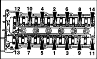
* Tighten the cylinder head bolts with particular care. Before tightening the bolts, check the torque wrench for accuracy. In addition, an angle-measuring washer, for example HAZET 6690, is required to tighten the bolts. If no such washer is available, attach a ruler of an angle gauge to the wrench handle and mark the corresponding angle with chalk. Then turn the wrench in one pass through the marked angle.
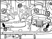
11. Install and tighten the camshaft sprocket cover bolts. (Refer to the accompanying illustration).
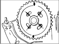
12. Install the sprocket on the camshaft flange. The arrow on the sprocket must point upward. The threaded holes must be on the left side of the oblong holes, because the sprocket turns to the left when the tensioner is installed. Refer to the accompanying illustration.
13. Install the chain guide and the upper tensioner.
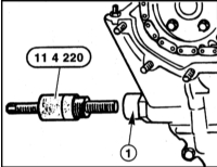
14. Screw special BMW tool 11 4 220 into the threaded hole of the chain tensioner. Refer to the accompanying illustration.
This tool presses on the chain and applies preliminary tension, so that the camshaft sprockets can be positioned in the middle of the oblong holes. With some experience, this tool can be made independently. Without this tool, correct chain installation is not possible.
15. Install the thrust washer on the intake camshaft and tighten to 20 N·m. Refer to the accompanying illustration.
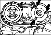
16. Fit the upper chain together with the sprockets, making sure of correct position. The flat side of the sprocket must face outward, the collar toward the camshaft. Refer to the accompanying illustration.
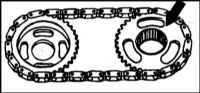
17. The arrow on the exhaust camshaft sprocket must point upward. The mounting bolts must be located in the middle of the oblong holes. Refer to the accompanying illustration.
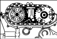
18. Version without disc springs: Install the thrust washer on the intake camshaft sprocket and tighten to 20 N·m. Refer to the accompanying illustration.
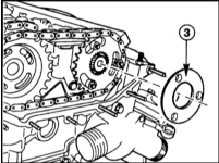
19. Version with disc springs:
Install the thrust washer (approx. 2 mm thick) on the intake camshaft. Then install the disc spring (2). Observe the position of the disc spring: the large diameter must point in the direction of the camshaft. Then install the thrust washer (approx. 4 mm thick). Install the three nuts, applying Loctite 270 thread locking compound to the threads, and tighten to 20 N·m.
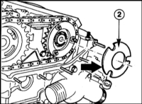
20. Screw in the exhaust camshaft sprocket bolts without tightening them.
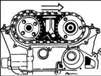
21. Before installing the VANOS adjusting element, turn both sprockets in the oblong holes fully to the right. Refer to the accompanying illustration.
22. Before installation, press the VANOS toothed shaft (1) fully in the direction of the housing (2). Refer to the accompanying illustration.
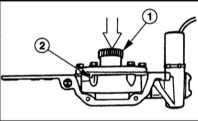
23. Note the locating sleeves (1). Fill the corners of the sealing surfaces between the cylinder head and the VANOS unit with Drei Bond 1209 sealant. Refer to the accompanying illustration.
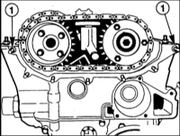
24. Install the VANOS adjusting element. The toothed shaft engages in the sprocket. To allow engagement, turn the sprocket by hand or, on the version with disc spring, counterclockwise using an auxiliary tool.
* The first suitable tooth must engage. Otherwise the camshaft timing will be incorrectly adjusted. Refer to the accompanying illustration.
25. Move the VANOS unit toward the cylinder head. The sprocket rotates to the left due to the inclination of the tooth. Support this movement by turning the sprocket by hand.
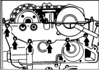
26. Install and tighten the VANOS adjusting unit mounting bolts. Refer to the accompanying illustration.

27. Release the upper tensioner by removing tool 11 3 292. Refer to the subsection "Removal".
28. Apply preliminary tension by turning the tensioner bolt with the special tool to 1.3 N·m. Refer to the accompanying illustration.
29. In this position, tighten the exhaust camshaft sprocket bolts to 20 N·m in two stages, evenly and in a crisscross pattern.
Remove the special tool used to lock the camshaft and pre-tension the chain.
* BMW workshops check the VANOS unit using a special tool. If the vehicle runs perfectly after assembly, the check does not have to be performed immediately and can be carried out later.
30. Secure the oil line to the VANOS unit with new seals. Connect the plug connector.
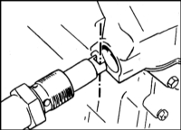
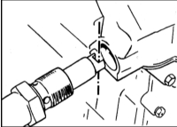
31. Screw in the lower chain tensioner with a new O-ring and tighten to 35 N·m. Make sure the tensioner is positioned correctly. The groove on the piston must be perpendicular to the tensioning rail. Refer to the accompanying illustration.
32. Install the timing case cover with a new gasket. Tighten the M6 cover bolts to 10 N·m and the M8 bolts to 22 N·m. Do not forget the locating sleeves at the outer bolts.
33. Screw in the three cylinder head cover pins.
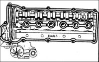
34. Install the cylinder head cover. Replace damaged gaskets. When fitting the gasket, pay special attention to its correct position in the grooves of the cylinder head face. Tighten the cylinder head cover evenly to 10 N·m. Refer to the accompanying illustration.
35. Insert the cylinder identification sensor and secure it. If the O-ring is damaged, replace it.
36. Install the spark plugs. Refer to the Spark Plug Inspection and Replacement section.
37. Install the intake manifold. Refer to the Intake Manifold Removal and Installation section.
38. Connect the electrical wires. Refer to the "Removal" subsection.
Secure the exhaust pipe to the exhaust manifold.
* Before starting the engine, remove the TDC locking pin from the flywheel.
39. Fill the cooling system with coolant. Refer to the Coolant Replacement section. Coolant Antifreeze Check. Visual Inspection of the Cooling System.
40. Check the engine oil level. Top up the oil if necessary. If the cylinder head was removed due to a faulty head gasket, it is recommended to replace the engine oil beforehand, including the oil filter, as coolant may be present in the engine oil.
525tds models (M51 engine)
Signs of a faulty cylinder head gasket are listed above.
REMOVAL
1. Disconnect the negative battery cable. The battery is located in the luggage compartment behind the right side trim panel.
* Disconnecting the battery erases data stored in electronic control unit memories, such as the engine fault memory. Refer to the recommendations in the Battery Removal and Installation section.
2. Drain the coolant and dispose of it. Refer to the Coolant Replacement section. Coolant Antifreeze Check. Visual Inspection of the Cooling System.
3. Remove the hose from the thermostat housing after opening the clamp.
4. Drain the coolant from the engine. To do so, remove the plug on the side of the cylinder block below the exhaust manifold. Reinstall the plug immediately after the coolant has drained.
5. Disconnect the fan with viscous coupling (left-hand thread). Refer to the Fan and Fan Clutch Removal and Installation section.
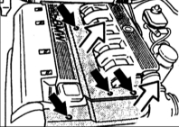
6. Remove the engine covers at the intake manifold. Refer to the accompanying illustration.
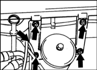
7. Remove the intake manifold brackets. Refer to the accompanying illustration.
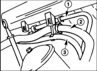
8. Remove the following hoses from the cylinder head holder: 1 - brake booster vacuum hose, 2 - heater coolant hose, 3 - fuel hose to the injection pump. Refer to the accompanying illustration.
9. Disconnect the vacuum hose at the intake port (at the exhaust gas recirculation valve).
10. Disconnect the intake manifold temperature sensor electrical wires by pressing the wire clip.
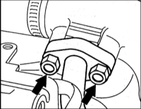
11. Unscrew the bolts securing the exhaust gas recirculation pipe to the intake manifold. Open the clamp and disconnect the air hose from the intake manifold. Refer to the accompanying illustration.
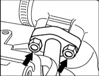
12. Unscrew the mounting bolts and remove the intake manifold. Refer to the accompanying illustration.
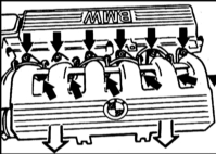
13. Unscrew the union nuts of the injection lines from the injectors and the fuel injection pump. A BMW or HAZET No. 4550 special wrench is required. Close the openings with blanking plugs. Refer to the accompanying illustration.

14. Disconnect the glow plug terminals. Refer to the accompanying illustration.

15. Disconnect the plug connector of the injection start sensor at the injector.
16. Disconnect the exhaust gas recirculation pipe at the exhaust manifold and at the bracket, then remove it. Refer to the accompanying illustration.

17. Remove the V-belt. Refer to the V-Belt Removal, Installation and Tensioning section.
18. Unscrew the mounting bolts and remove the turbocharger from the exhaust pipe. Refer to the accompanying illustration.
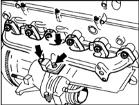
19. Evenly loosen all cylinder head cover bolts by 1/2 turn first, then remove them completely. Remove the cover. Refer to the accompanying illustration.
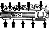
20. Disconnect the hydraulic V-belt tensioner and remove the damper.
* Store the removed tensioner only in its working position, i.e. upright. Otherwise, malfunctions in its operation may occur later. Refer to the accompanying illustration.
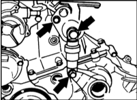
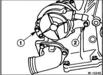
21. Unscrew the two mounting bolts and remove the vacuum pump. Bolt (2) also serves as the holder for the chain guide. The bolt must be sealed with sealant. After removal, the bolt must be either replaced with a new one or coated with sealant. Refer to the accompanying illustration.
22. Set the piston of the No. 1 cylinder to TDC. The cams of the intake and exhaust camshafts of the No. 1 cylinder must face upward. The engine can be turned as follows:
a) Engage 5th gear and move the vehicle on a level surface.
b) Using a socket on the center bolt of the crankshaft pulley, turn in the direction of rotation (the manual transmission must be in neutral).
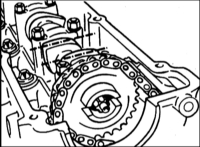
23. Lock the crankshaft at TDC using tool 11 2 300 or a suitable pin. To do this, insert the pin through the hole in the cylinder block into the hole in the flywheel, after first removing the plug. Refer to the accompanying illustration.
* Do not turn the crankshaft or camshafts after the cylinder head has been removed.
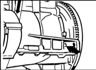
24. Lock the camshaft using BMW tool. It is possible to do without the tool, but when loosening the camshaft sprocket bolt, hold the 27 mm hex from turning. Refer to the accompanying illustration.
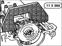
25. Install the lever on the chain guide and press down the tensioner. Refer to the accompanying illustration.

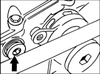
26. Unscrew the plug and lock the tensioner in the depressed position with a suitable pin. Refer to the accompanying illustration.
27. Unscrew the camshaft sprocket bolts and remove the sprocket while holding the shaft by the hex. To prevent the chain from slipping down, secure it with wire.
28. Unscrew the guide rail retaining pin at the cylinder head and remove it along with the sealing ring. Refer to the accompanying illustration.
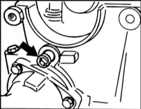
29. Unscrew the chain guide retaining pin and remove it along with the sealing ring. Refer to the accompanying illustration.
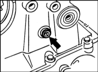
30. Unscrew the studs securing the drive sprocket cover. Refer to the accompanying illustration.
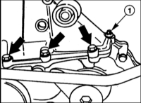
31. Unscrew the bolt (arrow in the accompanying illustration) and disconnect the drain hose from the injector.
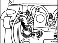
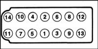
32. Loosen the cylinder head bolts in sequence 14 to 1, by 1/2 turn. Then remove them in the same sequence. A Torx socket size E12 is required to remove the bolts. Refer to the accompanying illustration.
33. Remove the cylinder head.
* Do not place the cylinder head on its sealing surface after removal. The fully open valves may be damaged. Place the cylinder head on two wooden blocks.
INSTALLATION
1. Before installation, clean the cylinder head and block sealing surfaces of old gasket material and sealant using a suitable scraper. Make sure sealant does not get into the holes. Cover the holes with a rag.
2. Check the cylinder head and block surfaces for flatness in the longitudinal and transverse directions using a steel straightedge.
* Do not machine the cylinder head. If damaged, replace the cylinder head.
3. Check that the locating sleeves are in the correct position (arrows in the accompanying illustration). They center the gasket and the cylinder head.
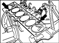
4. Thoroughly blow out the cylinder head bolt holes with compressed air to remove oil and sealant residue, or clean them with a rag wrapped around a screwdriver.
* Oil must not accumulate in the blind holes, as this may affect correct torque measurement of the bolts. It may also cause the cylinder block to crack.
5. Always replace the cylinder head gasket and cylinder head bolts with new ones.
6. Place the new cylinder head gasket without additional sealant so that it does not block the holes. Depending on its thickness, the gasket is marked with a different number of holes. The new gasket must have the same number of holes as the old one. Refer to the accompanying illustration.
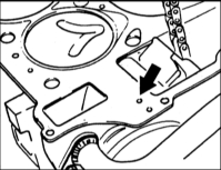
7. If it is unclear which gasket must be installed, for example after repair of the cylinder block, measure the piston protrusion with a dial indicator. Select the gasket according to the largest protrusion of any of the six pistons. To do this, position the dial indicator at point (A) and, by turning the crankshaft slightly in both directions, determine the largest protrusion. Then repeat the measurement at point (B). Refer to the accompanying illustration.
The average of the measurements (A) and (B) is the piston protrusion. Perform these measurements at all six points.
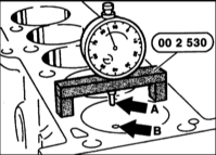
8. Calculate the average of the obtained values. To do this, add all protrusions together and divide by six. If the result is less than 0.76 mm, install a gasket with two holes. If the value is greater than 0.76 mm, install a gasket with three holes.
* If one or more cylinders have a piston protrusion greater than 0.81 mm, install a gasket with three holes.
9. For versions with the injection pump bracket only: Replace the profile rubber seal with a new one. Clean the seal groove. Apply "Drei Bond 1209" sealant to the ends of the grooves.
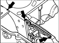
10. Seal the joints between the drive sprocket cover and the cylinder head with "Drei Bond 1209" sealant. Refer to the accompanying illustration.
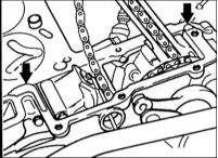
11. Install the cylinder heads with the help of an assistant. Do not tilt the cylinder heads, as this may damage the gasket.
* Do not turn the crankshaft or camshafts after removal, as open valves may contact the pistons. If necessary, turn the shafts to the required position before installation; refer to the "Removal" subsection. Refer to the accompanying illustration. The illustration shows the high-pressure fuel pump drive sprocket of the diesel engine. The marking must face upward.
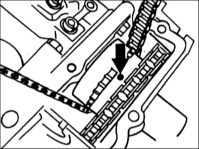
12. Lightly lubricate the new cylinder head bolts and screw them in by hand.
* Cylinder head bolts must be tightened with particular care. Check the torque wrench for accuracy before tightening the bolts. An angle gauge, such as HAZET 6690, is also required to tighten the bolts. Place the torque wrench along the cylinder block and mark the angle with chalk using the angle gauge on the cylinder head.
13. Tighten the cylinder head bolts in six stages in sequence 1 to 14. Refer to illustration 6.107. Torque values are given in the Specifications.
14. Install the timing chain cover and tighten its mounting bolts to 10 N·m.
15. Tighten the bolts next to the injector and install the oil drain hose next to the injector. Refer to the "Removal" subsection.
16. Screw in the two pins of the tensioner rail and chain guide with new O-rings.
17. Secure the camshaft sprocket with the chain on the camshaft. Do not tighten the bolts.
* Mating surfaces must be degreased and cleaned.
18. Remove the locking tool from the tensioner so that the chain is tensioned. Install the plug into the hole.
19. If the camshaft is locked with the BMW camshaft setting tool: The tool is intended for chain adjustment at vehicle mileage up to 20,000 km. At higher mileage, place a shim (feeler gauge) with thickness A = 4.5 mm on the intake valve side of the cylinder head. If the tool is not used, turn the camshaft 2° counterclockwise and hold it in this position by the 27 mm hex. Refer to the accompanying illustration.
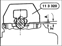
20. In this position, tighten the camshaft sprocket in two stages to the torque given in the Specifications (refer to the accompanying illustration).
* Remove the flywheel locking tool from the crankshaft and the camshaft locking tool. Turn the engine by hand several times and check the valve timing. Refer to the accompanying illustration.

21. Install the vacuum pump with a new O-ring. The drive tang must engage the slot in the camshaft sprocket. Refer to the accompanying illustration.
* The Torx bolt on the camshaft sprocket has a hole for lubricating the vacuum pump. Clean the hole if necessary.
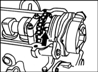
22. Tighten the two vacuum pump mounting bolts to 20 N·m. Either replace the inner bolt with a new one or coat it with liquid sealant before installation, as it requires sealing.
23. Install the damper and chain tensioner bracket and secure them.
24. Install the drive belt. Refer to the Section Removal, Installation and Tensioning of Drive Belt.
25. Check the cylinder head cover gasket and replace it if necessary.
26. Install the cylinder head cover and tighten the mounting bolts from the inside out to 15 N·m. Make sure the gasket is correctly seated in the groove. Refer to the accompanying illustration.
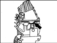
27. Install the turbocharger with a new gasket and new self-locking nuts on the exhaust manifold. Apply copper (high-temperature) paste to the bolts beforehand. Tighten all bolts to 45 N·m.
28. Install the glow plug connections.
29. Connect the plug connector of the injection timing sensor at the injector.
30. Install the injector lines without bending them. Tighten the union nuts to 20 N·m using a special wrench.
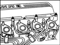
27. Install the turbocharger with a new gasket and new self-locking nuts on the exhaust manifold. Apply copper (high-temperature) paste to the bolts beforehand. Tighten all bolts to 45 N·m.
28. Install the glow plug connections.
29. Connect the plug connector of the injection timing sensor at the injector.
30. Install the injector lines without bending them. Tighten the union nuts to 20 N·m using a special wrench.
31. Replace the intake manifold gaskets with new ones. Then install the intake manifold. Tighten the mounting bolts in a crosswise sequence to 25 N·m.
32. Tighten the intake manifold support bolts.
33. Route or install all hoses in the intake manifold holder. Refer to the "Removal" subsection.
34. Secure the exhaust gas recirculation pipe to the exhaust manifold, the holder and the intake manifold.
35. Connect the electrical wires.
36. Connect the ground cable to the battery. Set the clock. Program the radio stations.
37. Install the coolant hose on the thermostat housing and secure it with a clamp.
38. Fill the cooling system with coolant. Refer to the Section Coolant Replacement. Coolant Freeze Protection Check. Visual Inspection of Cooling System.
39. Install the fan with viscous coupling (left-hand thread). Refer to the Section Removal and Installation of Fan and Fan Clutch.
40. Check the engine oil level. Top up if necessary. If the cylinder head was removed due to a faulty head gasket, it is recommended to replace the oil, including the oil filter, as the oil may contain coolant.
* Let the engine warm up for 25 min. Remove the cylinder head cover and tighten the head bolts with a solid wrench in the specified sequence by an angle of 90°. The tightening sequence is shown in the illustration.
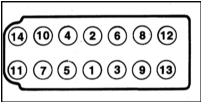
41. For precise bolt tightening, an angle gauge, such as HAZET 6690, is required. Place the torque wrench along the cylinder block and mark the angle with chalk using the angle gauge on the cylinder head.
42. Install the cylinder head cover and tighten the mounting bolts in a crosswise sequence to 15 N·m.
43. Install the engine cover in place.
Test yourself
A quick BMW 1 quiz: every answer comes with an explanation and a link to the manual page.