Testing, Removal and Installation of the Temperature Sensor
Both temperature sensors measure the coolant temperature and the intake air temperature and send the signals to the control module. The sensors contain an NTC (Negative Temperature Coefficient) element, which decreases its resistance as temperature increases. If the coolant temperature sensor is faulty, the control module uses a substitute resistance value at +80°C. A faulty sensor at low outside temperature and a cold engine causes starting problems and unstable engine operation.
TESTING
1. Disconnect the plug connector of the relevant sensor. For sensor locations, refer to the Removal subsection.
2. Connect an ohmmeter to the sensor terminals.
3. Measure the resistance and compare it with the specified value. Specified values are given in the Specifications.
4. If the resistance does not match the specified value, remove the sensor.
5. Secure the sensor with wire and lower it into a container of water so that it does not touch the walls. Cool the water with ice, then heat it on a hotplate. At the specified temperature, remove the sensor and measure the resistance between the terminals. If the resistance does not match the specified value, replace the sensor.
6. If the sensor is serviceable, connect a voltmeter between the sensor connector terminal and ground.
7. Turn the ignition on. Required value: approximately 5 V. If there is no voltage, check the supply wire for serviceability.
8. Check the ground wire, if equipped.
9. If the wiring and temperature sensors are in order, look for the fault elsewhere.
Removal of Coolant Temperature Sensor
PROCEDURE
1. To prevent coolant from leaking out during sensor removal, partially drain the coolant beforehand. Refer to Coolant Replacement. Coolant Freeze Protection Check. Visual Inspection of Cooling System.
11 Remove the engine cover at the intake manifold and disconnect the crankcase ventilation connection at the cylinder head, as described in Intake Manifold Removal and Installation.
2. The coolant temperature sensor is located under the intake manifold at the front of the engine (arrow in the accompanying illustration).

3. Disconnect the plug connector and remove the sensor.
INSTALLATION
1. Screw in the temperature sensor with a new O-ring and tighten to 20 N·m.
15 Connect the plug connector and secure it with the clip.
16 Secure the crankcase ventilation hose to the cylinder head. Install the engine cover.
17 Fill the system with coolant and bleed the air from it. Refer to Coolant Replacement. Coolant Freeze Protection Check. Visual Inspection of Cooling System.
18 Drive the vehicle and check the temperature sensor connection for leaks. Retighten the connection if necessary.
19 Read the fault memory of the DME control unit. After repairing the faults, clear the memory.
Removal of Intake Air Temperature Sensor
20 Remove the mounting screws and the throttle body connector. Refer to Throttle Body Connector Removal and Installation.
* Do not disconnect the throttle linkage and the throttle heater coolant hoses.
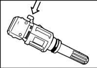
2. Press the locking button (arrow in the accompanying illustration) on the temperature sensor. Pull the sensor down out of the intake manifold.
INSTALLATION
1. Install the temperature sensor with a new gasket and tighten to 20 N·m.
2. Connect the plug connector and secure the plug with the clip.
3. Install the throttle body connector. Refer to Throttle Body Connector Removal and Installation.
4. Install the intake hose and secure it with the clamp.
5. Read the fault memory of the DME control unit. After repairing the faults, clear the memory.
Test yourself
A quick BMW 1 quiz: every answer comes with an explanation and a link to the manual page.