Powertrain
Disassembly - Transmission
In this manual: Powertrain
65steps
~415min
5/5difficulty
5special tools
Done 0 of 65
Special Service Tools / General Equipment
 |
307-163 (T86P-70043-A) Remover, Stator Housing Bearing TKIT-1986-LM TKIT-1986-F |
 |
307-586 Differential Bearing Cup Remover TKIT-2006UF-FLM TKIT-2006UF-RYAD |
 |
307-741 Spring Compressor, Clutch F |
 |
307-821 Motor Rotor Remover/Installer |
 |
308-001 (T58L-101-B) Guide Bearing Remover |
| Hydraulic Press | |
| Puller | |
| Strike with a fist | |
| Wood block | |
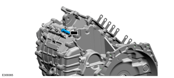
- Remove the vent assembly.
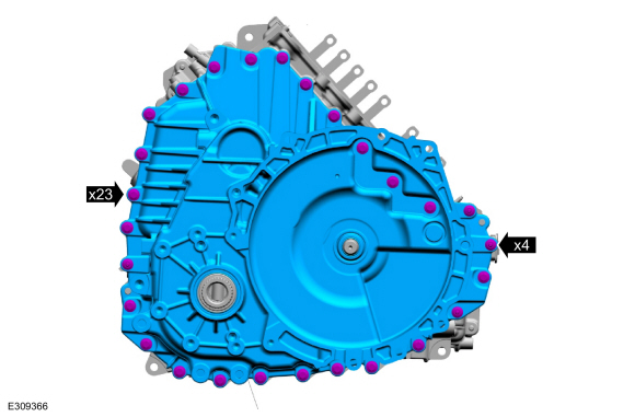
- Remove the damper housing bolts and studs.
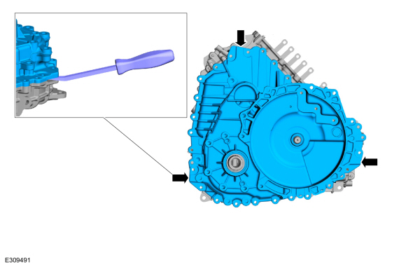
- Using a pry bar, pry the damper housing at the indicated locations to remove the housing.
- Remove the output shaft gear assembly and the traction motor drive gear assembly.
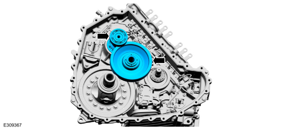
- Replace the output shaft and gear assembly and install new bearing rings if the bearings are damaged.
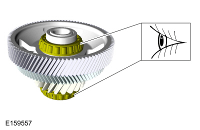
- Replace the output shaft and gear assembly and install new bearings if the bearings are damaged.

- Using a pry bar and a wooden block, remove the final drive input gear assembly.
Use common equipment: wooden block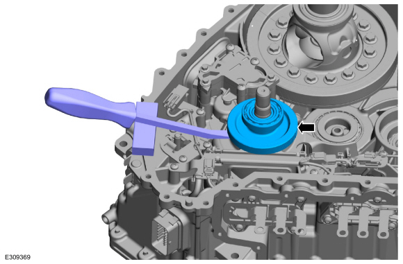
- Replace the final drive input gear assembly if the bearings are damaged.
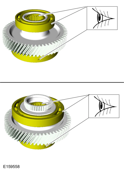
- Remove the differential case gear assembly.
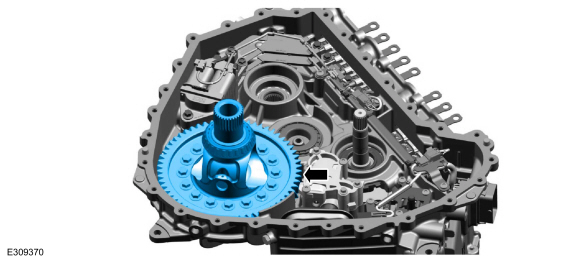
- Inspect the differential bearing for damage and replace if necessary.
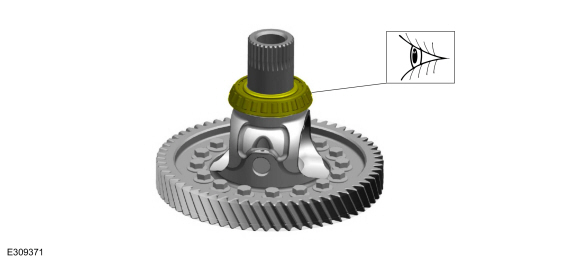
- Using the special service tools, remove the transaxle output shaft gear side bearing cup.
Use special service tool: 308-001 (T58L-101-B) Guide Bearing Remover, 307-163 (T86P-70043-A) Stator Housing Bearing Remover.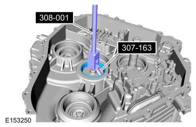
- Remove and discard the left axle seal.
Use common equipment: slide hammer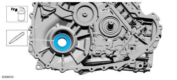
- Position the differential bearing cup remover 307-586 in the transaxle case with the tabs on the differential bearing cup remover 307-586 aligned with the slots in the transaxle case.
Use special service tool: 307-586 Differential Bearing Remover.
- Expand the differential bearing cup remover 307-586 by hand.
- Hold the differential bearing cup remover 307-586 in the expanded position with the tabs in the transaxle case slots, and tighten the nut.
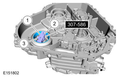
- Position the differential bearing cup remover 307-586 in the transaxle case with the tabs on the differential bearing cup remover 307-586 aligned with the slots in the transaxle case.
- Using a hammer and a drift, remove the differential bearing cup.
Use special service tool: 307-586 Differential Bearing Remover.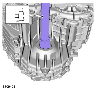
- Remove the clips and the transmission fluid pan baffle.
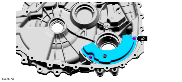
- Remove the clips and the transmission fluid manifold plate.
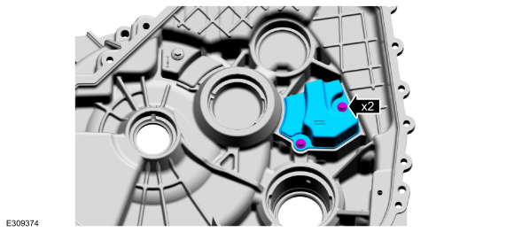
- Remove the clip and the transmission fluid manifold plate.
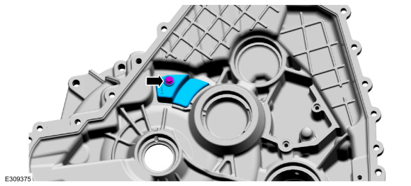
- Remove and discard the right axle seal.
Use common equipment: slide hammer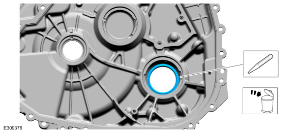
- Remove and discard the input shaft seal.
Use common equipment: slide hammer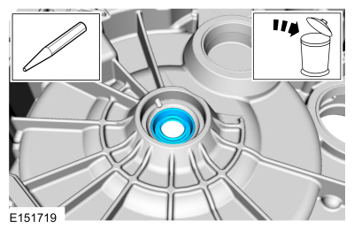
- Remove the transaxle output shaft gear side bearing cup from the damper housing.
Use special service tool: 308-001 (T58L-101-B) Guide Bearing Remover, 307-163 (T86P-70043-A) Stator Housing Bearing Remover.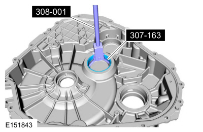
- Remove the output shaft preload adjustment shim.
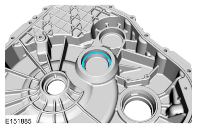
- Position the differential bearing cup remover 307-586 in the damper housing with the tabs on the differential bearing cup remover 307-586 aligned with the slots in the damper housing.
Use special service tool: 307-586 Differential Bearing Remover.
- Expand the differential bearing cup remover 307-586 by hand.
- Hold the differential bearing cup remover 307-586 in the expanded position with the tabs in the damper housing slots, and tighten the nut.
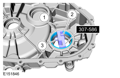
- Position the differential bearing cup remover 307-586 in the damper housing with the tabs on the differential bearing cup remover 307-586 aligned with the slots in the damper housing.
- Using a hammer and a drift, remove the differential side bearing cup from the damper housing.
Use special service tool: 307-586 Differential Bearing Remover.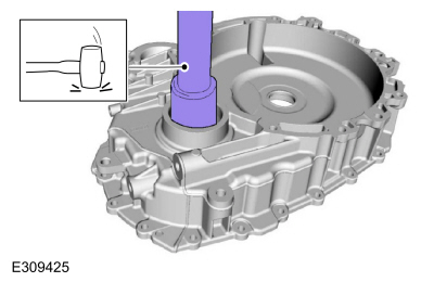
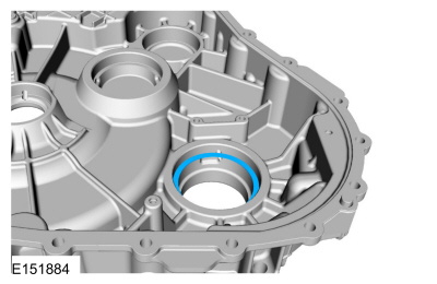
- Remove the differential adjustment shim.
- Remove the traction motor drive gear rear bearing from the traction motor drive gear.
Use common equipment: puller
Use common equipment: hydraulic press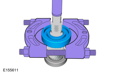
- Remove the traction motor drive gear front bearing from the traction motor drive gear.
Use common equipment: puller
Use common equipment: hydraulic press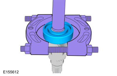
- Remove the transaxle high-voltage terminals.
Refer to: Transaxle High-Voltage Terminals (307-01B Automatic Transmission - Automatic Transmission - HF45, Disassembly and Assembly of Sub-Assemblies). - Disconnect the traction motor stator electrical connector.
- Disconnect the generator/starter stator electrical connector.
- Disconnect the wiring harness retainer.
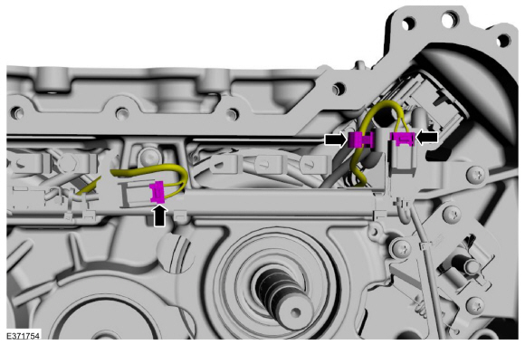
- Position the transmission case on wooden blocks so that the transmission input shaft does not contact the bench surface.
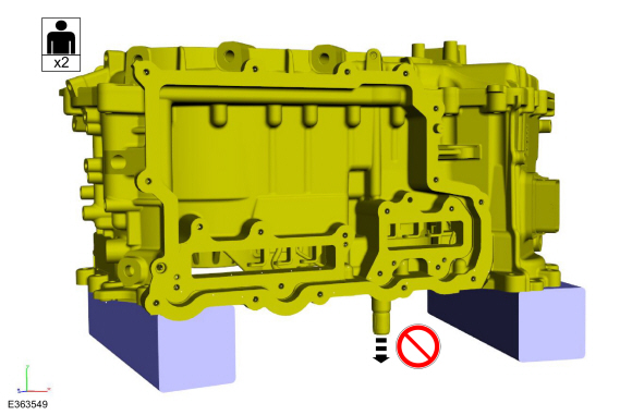
- Remove the transmission case cover.
Refer to: Transmission Case Cover (307-01B Automatic Transmission/Transaxle - Automatic Transmission/Transaxle - HF45, Removal and Installation). - Using a straightedge, measure and record the distance between the traction motor rotor and the transmission case surface. Then measure and record the distance between the generator/starter rotor and the transmission case surface for reassembly.
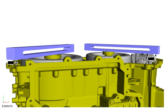
- Mark the traction motor stator and the generator/starter stator to the transmission case as a reference for correct installation.
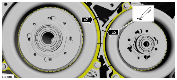
- Remove the traction motor stator bolts.
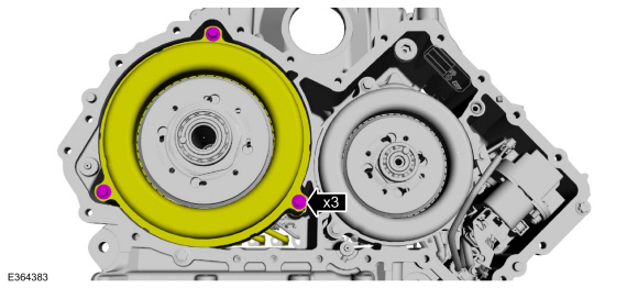
- Install the special tool to the traction motor stator windings.
Use special service tool: 307-821 Motor Rotor Remover/Installer.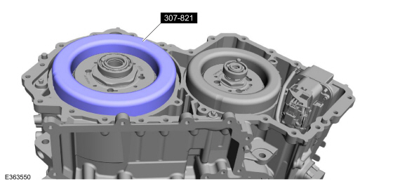
- Install the special tool into the traction motor rotor slot holes and turn counterclockwise until the special tool is secured.
Use special service tool: 307-821 Motor Rotor Remover/Installer.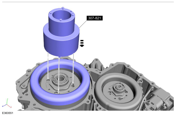
- Install the pin into the special tool until it is fully seated in the rotor.
Use special service tool: 307-821 Motor Rotor Remover/Installer.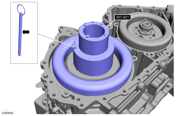
- Install the special tools, thread the tension bolt into the special tool and tighten the wing nuts.
Use special service tools: 307-741 Spring Compressor, Clutch F, 307-821 Motor Rotor Remover/Installer.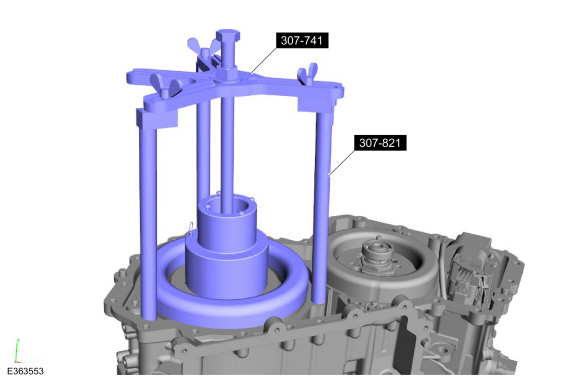
NOTICE: The rotors are magnetized. Place them only on a non-metallic tray.
- Remove the traction motor rotor by turning the nut on the drawbar.
- When the rotor begins to move out of the stator, lift the special tool to remove the rotor.

- Remove the generator/starter stator bolts.
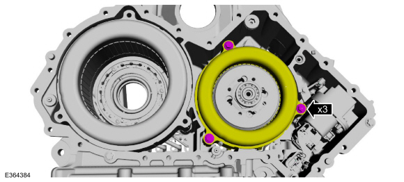
- Install the special tool to the generator/starter stator windings.
Use special service tool: 307-821 Motor Rotor Remover/Installer.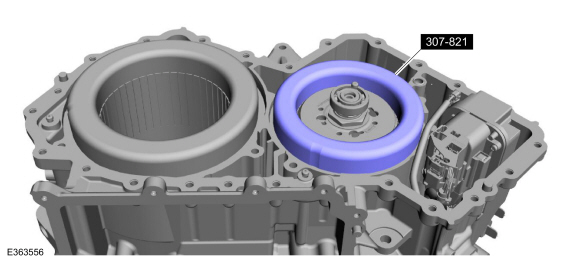
- Install the special tool into the generator/starter rotor slots and turn counterclockwise until the special tool is secured.
Use special service tool: 307-821 Motor Rotor Remover/Installer.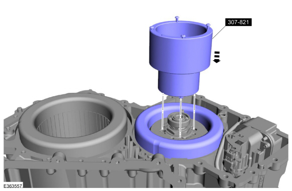
- Install the pin into the special tool until it is fully seated in the rotor.
Use special service tool: 307-821 Motor Rotor Remover/Installer.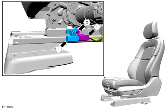
- Install the special tools, thread the tension bolt into the special tool and tighten the wing nuts.
Use special service tools: 307-741 Spring Compressor, Clutch F, 307-821 Motor Rotor Remover/Installer.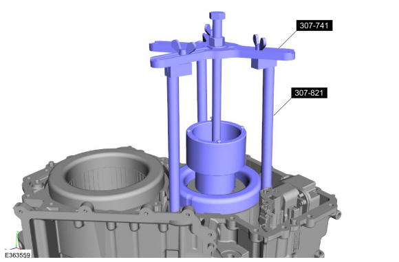
NOTICE: The rotors are magnetized. Place the rotors only on a non-metallic tray. Do not allow the traction rotor and the generator/starter rotor to contact each other, as damage may occur.
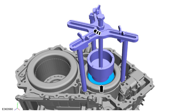
- Remove the generator/starter rotor by turning the nut on the drawbar clockwise.
- When the rotor begins to move out of the stator, lift the special tool to remove the rotor.
- If equipped, cut and discard the tie strap.
- Disconnect the park lock actuator.
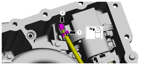
NOTICE: When removing the stator, be careful not to bend or break the stator wires.
NOTICE: After removing the stator, lay the stator on its side, otherwise damage to the windings may occur.
Remove the generator/starter stator.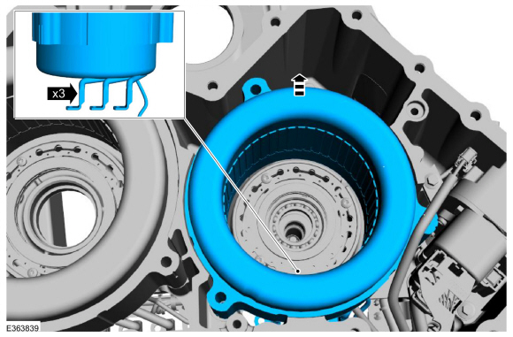
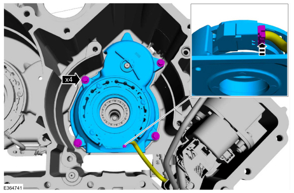
- Remove the planetary carrier support cover bolts, disconnect the generator/starter resolver and remove the support cover.
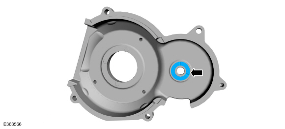
- Remove the thrust washer from the planetary carrier support cover.
- Remove the pump drive gear.
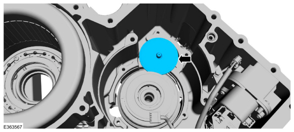
- Remove the sun gear.
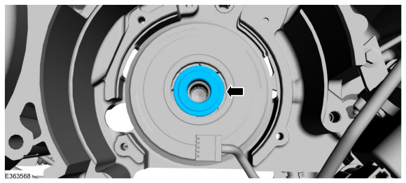
- Remove the sun gear thrust bearing.
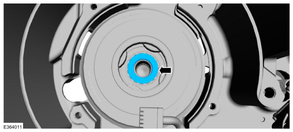
- Remove the planetary carrier assembly.
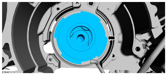
- Remove the ring gear.
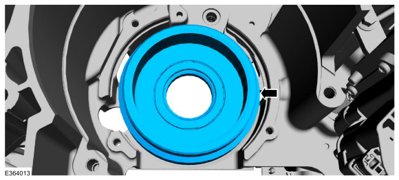
NOTICE: When removing the stator, be careful not to bend or break the stator wires.
NOTICE: After removing the stator, lay the stator on its side, otherwise damage to the windings may occur.
Turn the transmission case on its side and remove the traction motor stator.
- Using a metal scribe, mark the traction motor resolver and the transmission case as a reference for correct installation.
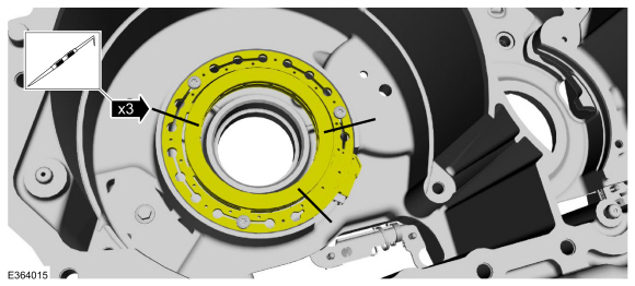
- Remove the traction motor resolver bolts.
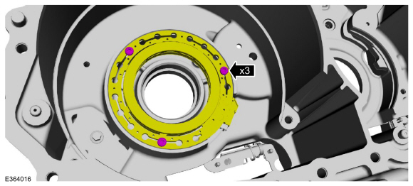
- Disconnect and remove the traction motor resolver.

- Disconnect the park lock actuator.
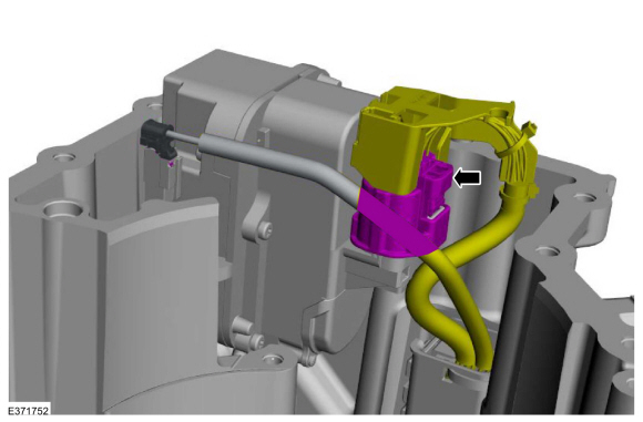
- Remove the park lock bolts and the park lock actuator.
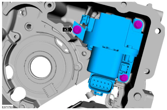
- Turn the transmission case over and position it on wooden blocks.

- Remove the wiring harness bolts.
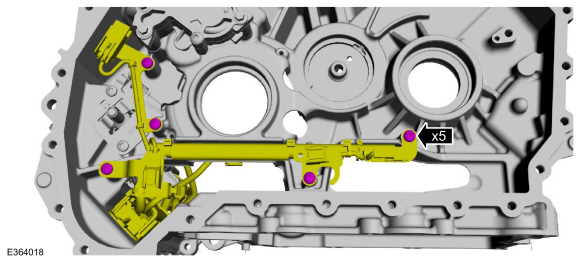
- Disconnect the wiring harness bulkhead connector and remove the wiring harness from the transmission case.
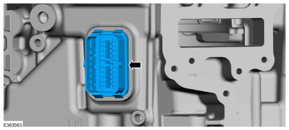
- Inspect the wiring harness bulkhead seal for damage. Replace if necessary.
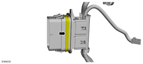
- Remove the bolts and the fluid pump and filter assembly.
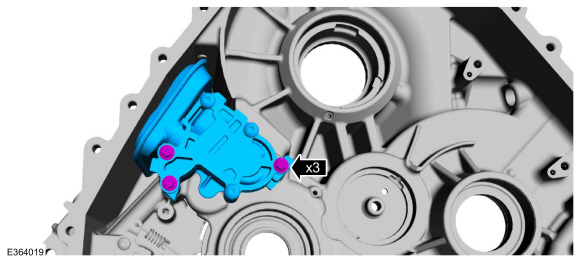
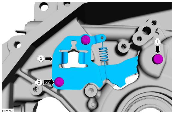
- Remove the park pawl shaft.
- Remove the park lock actuator guide bolts.
- Remove the park lock actuator guide and the park pawl.
Test yourself
A quick Ford Escape quiz: every answer comes with an explanation and a link to the manual page.
Was this page helpful?