Powertrain

Diagnosis and Testing - Automatic Transmission

~72min read

Diagnostic Trouble Code (DTC) Chart

The diagnosis in this manual assumes a certain level of skill and knowledge of Ford-approved diagnostic procedures.
REFER TO: Diagnostic Methods (100-00 General Information, Description and Operation).


Module Trouble Code Description Action
SOBDMC P0711:00 Transmission Fluid Temperature Sensor "A" Circuit Range/Performance: No Sub Type Information GO to Pinpoint Test A
SOBDMC P0712:00 Transmission Fluid Temperature Sensor "A" Circuit Low: No Sub Type Information GO to Pinpoint Test A
SOBDMC P0713:00 Transmission Fluid Temperature Sensor "A" Circuit High: No Sub Type Information GO to Pinpoint Test A
SOBDMC P07B5:00 Transmission Park Position Sensor/Switch "A" Circuit Low: No Sub Type Information GO to Pinpoint Test B
SOBDMC P07B6:00 Transmission Park Position Sensor/Switch "A" Circuit High Performance: No Sub Type Information GO to Pinpoint Test B
SOBDMC P07BB:00 Transmission Park Position Sensor/Switch "B" Circuit Low: No Sub Type Information GO to Pinpoint Test B
SOBDMC P07BE:00 Transmission Park Position Sensor/Switch Correlation "A" / "B": No Sub Type Information GO to Pinpoint Test B
SOBDMC P07E4:00 Unable to Engage Park: No Sub Type Information GO to Pinpoint Test E
SOBDMC P07E6:00 Stuck in Park: No Sub Type Information GO to Pinpoint Test E
SOBDMC P0972:00 Shift Solenoid "A" Control Circuit Range/Performance: No Sub Type Information GO to Pinpoint Test F
SOBDMC P0974:00 Shift Solenoid "A" Control Circuit High: No Sub Type Information GO to Pinpoint Test F
SOBDMC P0975:00 Shift Solenoid "B" Control Circuit Range/Performance: No Sub Type Information GO to Pinpoint Test G
SOBDMC P0977:00 Shift Solenoid "B" Control Circuit High: No Sub Type Information GO to Pinpoint Test G
SOBDMC P097A:00 Shift Solenoid "A" Control Circuit/Open: No Sub Type Information GO to Pinpoint Test F
SOBDMC P097B:00 Shift Solenoid "B" Control Circuit/Open: No Sub Type Information GO to Pinpoint Test G
SOBDMC P0B0D:00 Transmission Electric/Auxiliary Fluid Pump Motor Control Module: No Sub Type Information GO to Pinpoint Test H
SOBDMC P0C27:00 Transmission Electric/Auxiliary Fluid Pump "A" Motor Current Low: No Sub Type Information GO to Pinpoint Test H
SOBDMC P0C28:00 Transmission Electric/Auxiliary Fluid Pump "A" Motor Current High: No Sub Type Information GO to Pinpoint Test H
SOBDMC P0C2A:00 Transmission Electric/Auxiliary Fluid Pump "A" Stalled: No Sub Type Information GO to Pinpoint Test H
SOBDMC P175A:00 Transmission Fluid Overtemperature - Electric Transmission Fluid Pump Disabled: No Sub Type Information GO to Pinpoint Test H
SOBDMC P26C3:00 Internal Control Module Transmission Range Sensor Performance: No Sub Type Information GO to Pinpoint Test B
SOBDMC P271A:00 Park/Neutral Position (PRNDL) Sensor Park Pawl Position "A" Circuit Low: No Sub Type Information GO to Pinpoint Test D
SOBDMC P272C:00 Park Pawl Actuator Motor Control Circuit: No Sub Type Information GO to Pinpoint Test C
SOBDMC P272C:12 Park Pawl Actuator Motor Control Circuit: Short to Battery GO to Pinpoint Test C
SOBDMC P272C:14 Park Pawl Actuator Motor Control Circuit: Short to Ground or Open GO to Pinpoint Test C
SOBDMC P272C:2A Park Pawl Actuator Motor Control Circuit: Stuck in Range GO to Pinpoint Test C
SOBDMC P2796:00 Transmission Fluid Pump Electrical Control Circuit: No Sub Type Information GO to Pinpoint Test H
SOBDMC P2797:00 Transmission Electric/Auxiliary Fluid Pump Performance/Stuck Off: No Sub Type Information GO to Pinpoint Test H
SOBDMC P27B2:00 Internal Control Module Transmission Range Control Performance: No Sub Type Information GO to Pinpoint Test I
SOBDMC P27B4:00 Internal Control Module Transmission Direction Control System Performance: No Sub Type Information GO to Pinpoint Test K
SOBDMC P2800:00 Transmission Range Sensor Circuit 'B' (PRNDL Input): No Sub Type Information GO to Pinpoint Test J
SOBDMC P2806:79 Transmission Range Sensor Alignment: Mechanical Linkage Malfunction GO to Pinpoint Test I
SOBDMC U103B:00 Invalid Internal Control Module Monitor Data Received from Rear Differential Control Module: No Sub Type Information GO to Pinpoint Test L

Pinpoint Tests


DIAGNOSTIC TEST A: DTCS P0711, P0712, P0713

Refer to Wiring Diagrams Cell 30 for schematic and connector information.

Normal Operation and Fault Symptoms

The TFT sensor is located in the transmission internal wiring harness. The resistance of the TFT sensor changes with temperature. The Inverter System Controller (ISC) monitors the voltage drop across the TFT sensor to determine the transmission fluid temperature.

DTC Fault Trigger Conditions

Trouble Code Description Fault Trigger Condition
SOBDMC P0711:00 Transmission Fluid Temperature Sensor "A" Circuit Range/Performance: No Sub Type Information The TFT sensor 5V reference is good, but the TFT sensor indicates a significant difference from the other two sensors in the transmission fluid.
SOBDMC P0712:00 Transmission Fluid Temperature Sensor "A" Circuit Low: No Sub Type Information TFT Sensor Voltage Low. Indicated temperature was above 643.5°F (340°C) for 2.5 seconds. Signal circuit shorted to ground.
SOBDMC P0713:00 Transmission Fluid Temperature Sensor "A" Circuit High: No Sub Type Information TFT Sensor Voltage High. Indicated temperature was below -39.9°F (-40°C) for 2.5 seconds. Signal circuit open or shorted to power supply circuit.

Possible Sources

  • Damaged or backed-out terminals, corrosion, loose wires, and missing or damaged seals
  • Circuit
  • TFT Sensor
  • Inverter System Controller (ISC)
A1 RETRIEVE AND RECORD ALL DTCS
  • NOTE: The Inverter System Controller (ISC) is called SOBDMC in the scan tool. Using the diagnostic scan tool, retrieve all Diagnostic Trouble Codes (DTCs). If DTC P06B1 is present, diagnose it first.

Are Diagnostic Trouble Codes (DTCs) P0711, P0712, P0713 present?
Yes GO to A2
No The system is currently operating correctly. The concern may have been caused by a loose or corroded connector. ADDRESS the root cause of any connector or terminal problems.
A2 CHECK THE TFT (TRANSMISSION FLUID TEMPERATURE) SENSOR INPUT VOLTAGE
  • Ignition OFF.
  • Disconnect the transmission C1111.
  • Inspect the connector for damage or spread terminals, corrosion, loose wires, and missing or damaged seals.
  • The ignition is on.
  • Action:
    Click to display the connectors
    Positive lead Measurement/Action Negative lead
    C1111-34 Ground

Is the voltage between 4.8 and 5.2 volts?
Yes GO to A3
No GO to A4
A3 CHECK THE TFT (TRANSMISSION FLUID TEMPERATURE) SENSOR VOLTAGE CIRCUIT FOR CORRECT RESISTANCE
  • Disconnect the Inverter System Controller (ISC) C199B.
  • Inspect the connector for damage or spread terminals, corrosion, loose wires, and missing or damaged seals.
  • Action:
    Click to display the connectors
    Positive lead Measurement/Action Negative lead
    C199B-23 C1111-34

Is the resistance less than 3 ohms?
Yes GO to A9
No REPAIR the circuit.
A4 CHECK THE TFT (TRANSMISSION FLUID TEMPERATURE) SENSOR SIGNAL CIRCUIT FOR AN OPEN
  • Ignition OFF.
  • Disconnect the Inverter System Controller (ISC) C199B.
  • Inspect the connector for damage or spread terminals, corrosion, loose wires, and missing or damaged seals.
  • Action:
    Click to display the connectors
    Positive lead Measurement/Action Negative lead
    C199B-23 C1111-34

Is the resistance less than 3 ohms?
Yes GO to A5
No REPAIR the circuit.
A5 CHECK THE TFT (TRANSMISSION FLUID TEMPERATURE) SENSOR SIGNAL CIRCUIT FOR A SHORT TO GROUND
  • Action:
    Click to display the connectors
    Positive lead Measurement/Action Negative lead
    C199B-23 Ground

Is the resistance greater than 10000 Ohms?
Yes GO to A6
No REPAIR the circuit.
A6 CHECK THE TFT (TRANSMISSION FLUID TEMPERATURE) SENSOR SIGNAL CIRCUIT CONNECTORS
  • Check C199B-23, component side and wiring side, for spread, damaged, or corroded terminals and/or pins.
  • Check C1111-34, component side and wiring side, for spread, damaged, or corroded terminals and/or pins.

Were any problems found?
Yes REPAIR the circuit.
No GO to A7
A7 CHECK THE TFT (TRANSMISSION FLUID TEMPERATURE) SENSOR SIGNAL CIRCUIT IN THE TRANSMISSION INTERNAL HARNESS FOR A SHORT TO GROUND
  • Connect the transmission C1111.
  • Action:
    Click to display the connectors
    Positive lead Measurement/Action Negative lead
    C199B-23 Ground

Is the resistance greater than 10000 Ohms?
Yes GO to A8
No INSTALL a new transmission.
REFER TO: Transmission (307-01B Automatic Transmission/Transaxle - HF45, Removal and Installation).
A8 CHECK DTC (DIAGNOSTIC TROUBLE CODE) P06B1
  • Connect the Inverter System Controller (ISC) C199B.
  • Using the diagnostic scan tool, retrieve all Diagnostic Trouble Codes (DTCs).

Is DTC P06B1 present?
Yes
No INSTALL a new ISC.
REFER TO: Inverter System Controller (307-01B Automatic Transmission/Transaxle - HF45, Removal and Installation).
A9 CHECK THE TFT (TRANSMISSION FLUID TEMPERATURE) SENSOR GROUND CIRCUIT FOR AN OPEN
  • Disconnect the ISC C199A.
  • Action:
    Click to display the connectors
    Positive lead Measurement/Action Negative lead
    C199B-23 C1111-34

Is the resistance less than 3 ohms?
Yes GO to A10
No REPAIR the circuit.
A10 CHECK THE TFT (TRANSMISSION FLUID TEMPERATURE) SENSOR RESISTANCE AT THE BULKHEAD CONNECTOR
  • Action:
    Positive lead Measurement/Action Negative lead
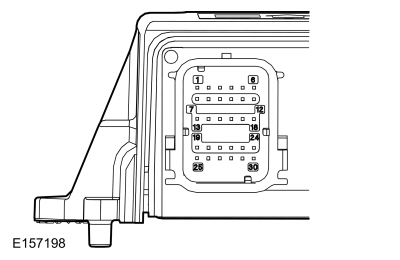
    Transmission connector, pin 34, component side Transmission connector, pin 24, component side

    Temperature and Resistance Table


    °F (°C) Ohms
    -39.9 to -4.0°F (-40 to -20°C) 1089-236 K
    -2.2 to 30.2°F (-19 to -1°C) 318K-83K
    32.0 to 68.0°F (0 to 20°C) 107K-33K
    69.8 to 103.9°F (21 to 40°C) 41K-14K
    105.7 to 157.9°F (41 to 70°C) 18K-5K
    159.7 to 193.9°F (71 to 90°C) 5.6K-2.6K
    195.7 to 229.8°F (91 to 110°C) 3.0K-1.4K
    231.6 to 265.8°F (111 to 130°C) 1.7-0.87K
    267.6 to 301.8°F (131 to 150°C) 0.97K-0.53K

Does the resistance match the temperature specification?
Yes GO to A11
No GO to A12
A11 CHECK THE CONNECTORS FOR CONTINUITY
  • Connect the transmission C1111.
  • Connect the ISC C199B.
  • The ignition is on.
  • Enter the following diagnostic mode: Data Logger.
  • Using the diagnostic scan tool, monitor the ISC TFT PID.
  • While monitoring the PID, perform the following:
    • Lightly tap on the transmission case connector and move the accessible harness from the transmission case assembly to the ISC.
    • Wiggle the transmission case connector for the ISC.
    • Look for sudden changes in temperature when the harness and connectors are moved or tapped.

Does the TFT temperature range change when the harness is moved or the connector is tapped?
Yes REPAIR the circuits as necessary. CLEAR the ISC diagnostic trouble codes (DTCs). REPEAT the self-test.
No The system is currently operating correctly. The concern may have been caused by a loose or corroded connector. ADDRESS the root cause of any connector or terminal problems.
A12 CHECK THE TFT (TRANSMISSION FLUID TEMPERATURE) SENSOR RESISTANCE AT THE SENSOR
  • Remove the damper housing.
    REFER TO: Transmission Case (307-01B Automatic Transmission/Transaxle - Automatic Transmission/Transaxle - HF45, Disassembly).
  • Disconnect the TFT sensor C1032.
  • Action:
    Positive lead Measurement/Action Negative lead
    TFT sensor, pin 1 TFT sensor, pin 2

    Temperature and Resistance Table


    °F (°C) Ohms
    -39.9 to -4.0°F (-40 to -20°C) 1089-236 K
    -2.2 to 30.2°F (-19 to -1°C) 318K-83K
    32.0 to 68.0°F (0 to 20°C) 107K-33K
    69.8 to 103.9°F (21 to 40°C) 41K-14K
    105.7 to 157.9°F (41 to 70°C) 18K-5K
    159.7 to 193.9°F (71 to 90°C) 5.6K-2.6K
    195.7 to 229.8°F (91 to 110°C) 3.0K-1.4K
    231.6 to 265.8°F (111 to 130°C) 1.7-0.87K
    267.6 to 301.8°F (131 to 150°C) 0.97K-0.53K

Does the resistance match the temperature specification?
Yes INSTALL a new transmission.
REFER TO: Transmission (307-01B Automatic Transmission/Transaxle - HF45, Removal and Installation).
No INSTALL a new TFT
REFER TO: Transmission Case (307-01B Automatic Transmission/Transaxle - Automatic Transmission/Transaxle - HF45, Disassembly).
DIAGNOSTIC TEST B: DTCS P07B5, P07B6, P07BB, P07BE, P26C3

Refer to Wiring Diagrams Cell 30 for schematic and connector information.

Normal Operation and Fault Symptoms

The park pawl motor moves the park pawl rod when power is applied, moving the park pawl out of the park position. When the park pawl is in the disengaged position, the park pawl motor is turned off and the Hold Oil Park Pawl (HOOP) solenoid is energized and holds the pawl in the open park position. When power is removed, a spring on the HOOP solenoid returns the park pawl to the park position. The park pawl actuator uses dual PWM outputs (at 1000 Hz) from the park pawl position sensors, where sensor A increases as the park pawl moves out of the park position and the sensor B signal decreases. Together, the sum of the two PWM duty cycle signals should total approximately 100%. The rotary sensor measures the position of the cam actuator that moves the linear park pawl rod and determines whether the park pawl actuator is in the Do Not Enter Park position.

DTC Fault Trigger Conditions

Trouble Code Description Fault Trigger Condition
SOBDMC P07B5:00 Transmission Park Position Sensor/Switch "A" Circuit Low: No Sub Type Information The ISC sets this DTC when the duty cycle or frequency of linear position sensor "A" is outside the acceptable limits.
SOBDMC P07B6:00 Transmission Park Position Sensor/Switch "A" Circuit High Performance: No Sub Type Information The ISC sets this DTC when the two linear position sensors do not correlate with each other.
SOBDMC P07BB: 00 Transmission Park Position Sensor/Switch "B" Circuit Low: No Sub Type Information The ISC sets this DTC when the duty cycle or frequency of linear position sensor "B" is outside the acceptable limits.
SOBDMC P07BE: 00 Transmission Park Position Sensor/Switch Correlation "A" / "B": No Sub Type Information The ISC sets this DTC when the two linear position sensors do not correlate with the rotary position sensor.
SOBDMC P26C3:00 Internal Control Module Transmission Range Sensor Performance: No Sub Type Information The ISC sets this DTC when the two linear position sensors are outside the acceptable limits or do not correlate with each other.

Possible Sources

  • Damaged or backed-out terminals, corrosion, loose wires, and missing or damaged seals
  • Communication
  • Circuit
  • Transmission Park Position Sensor
  • Park Lock Actuator
  • ISC
B1 RETRIEVE AND RECORD ALL DTCS
  • NOTE: The Inverter System Controller (ISC) is called SOBDMC in the scan tool. NOTE: If there is no communication between the GSM and the inverter system, diagnose any ISC diagnostic trouble codes (DTCs) first. NOTE: If the BCMC has any ePark-related diagnostic trouble codes (DTCs), diagnose them first. Using the diagnostic scan tool, retrieve all diagnostic trouble codes (DTCs).

Are any of the following DTCs present: P07B5, P07B6, P07BB or P07BE?
Yes GO to B2
No The system is currently operating correctly. The concern may have been caused by a loose or corroded connector. ADDRESS the root cause of any connector or terminal problems.
B2 CHECK THE VOLTAGE IN THE PARK POSITION SENSOR CIRCUIT
  • Disconnect the transmission C1111.
  • Inspect the connector for damage or spread terminals, corrosion, loose wires, and missing or damaged seals.
  • The ignition is on.
  • Action:
    Click to display the connectors
    Positive lead Measurement/Action Negative lead
    C1111-29 Ground

Is the voltage between 4.8 and 5.2 volts?
Yes GO to B8
No If the voltage is below 4.8 V, GO to B3.
If the voltage is above 5.2 V, GO to B6.
B3 CHECK THE PARK POSITION SENSOR CIRCUIT FOR AN OPEN
  • Ignition OFF.
  • Disconnect the Inverter System Controller (ISC) C199A.
  • Inspect the connector for damage or spread terminals, corrosion, loose wires, and missing or damaged seals.
  • Action:
    Click to display the connectors
    Positive lead Measurement/Action Negative lead
    C1111-29 C199A-37

Is the resistance less than 3 ohms?
Yes GO to B4
No REPAIR the circuit.
B4 CHECK THE PARK POSITION SENSOR VREF CIRCUIT FOR A SHORT TO GROUND
  • Action:
    Click to display the connectors
    Positive lead Measurement/Action Negative lead
    C1111-29 Ground

Is the resistance greater than 10000 Ohms?
Yes GO to B5
No REPAIR the circuit.
B5 RECHECK THE VOLTAGE IN THE PARK POSITION SENSOR CIRCUIT
  • Connect the Inverter System Controller (ISC) C199A.
  • The ignition is on.
  • Action:
    Click to display the connectors
    Positive lead Measurement/Action Negative lead
    C1111-29 Ground

Is the voltage between 4.8 and 5.2 volts?
Yes The cause is most likely a connector problem. INSPECT any loose or corroded terminals or pins.
No INSTALL a new Inverter System Controller (ISC).
REFER TO: Inverter System Controller (307-01B Automatic Transmission/Transaxle - Automatic Transmission/Transaxle - HF45, Removal and Installation).
B6 CHECK THE PARK POSITION SENSOR VREF CIRCUIT FOR A SHORT TO THE POWER CIRCUITS
  • Action:
    Click to display the connectors
    Positive lead Measurement/Action Negative lead
    C1111-29 C1111-1
    C1111-29 C1111-8
    C1111-29 C1111-11
    C1111-29 C1111-14
    C1111-29 C1111-15
    C1111-29 C1111-18
    C1111-29 C1111-28
    C1111-29 C1111-30
    C1111-29 C1111-34
    C1111-29 C1111-35
    C1111-29 C1111-38
    C1111-29 C1111-39
    C1111-29 C1111-40

Is the resistance greater than 10000 ohms?
Yes GO to B7
No REPAIR the circuit.
B7 CHECK FOR WATER IN THE HARNESS CONNECTORS
  • Check the connectors for water.

Are there any signs of water in the connectors?
Yes REPAIR as necessary.
No INSTALL a new Inverter System Controller (ISC).
REFER TO: Inverter System Controller (307-01B Automatic Transmission/Transaxle - Automatic Transmission/Transaxle - HF45, Removal and Installation).
B8 CHECK THE PARK POSITION RETURN CIRCUITS FOR AN OPEN
  • Ignition OFF.
  • Disconnect the Inverter System Controller (ISC) C199A.
  • Inspect the connector for damage or spread terminals, corrosion, loose wires, and missing or damaged seals.
  • For the park position sensor "A" measure:
    Click to display connectors
    Positive lead Measurement/Action Negative lead
    C1111-38 C199A-6
  • For the park position sensor "B" measure:
    Click to display connectors
    Positive lead Measurement/Action Negative lead
    C1111-18 C199A-17

Is the resistance less than 3 ohms?
Yes GO to B9
No REPAIR the circuit.
B9 CHECK THE PARK POSITION RETURN CIRCUITS FOR A SHORT TO GROUND
  • For the park position sensor "A" measure:
    Click to display connectors
    Positive lead Measurement/Action Negative lead
    C1111-38 Ground
  • For the park position sensor "B" measure:
    Click to display connectors
    Positive lead Measurement/Action Negative lead
    C1111-18 Ground

Is the resistance less than 3 ohms?
Yes GO to B10
No REPAIR the circuit.
B10 CHECK THE PARK POSITION RETURN CIRCUITS FOR A SHORT TO THE POWER CIRCUITS
  • For the park position sensor "A" measure:
    Click to display connectors
    Positive lead Measurement/Action Negative lead
    C1111-38 C1111-1
    C1111-38 C1111-8
    C1111-38 C1111-11
    C1111-38 C1111-14
    C1111-38 C1111-15
    C1111-38 C1111-18
    C1111-38 C1111-28
    C1111-38 C1111-29
    C1111-38 C1111-30
    C1111-38 C1111-34
    C1111-38 C1111-35
    C1111-38 C1111-39
    C1111-38 C1111-40
  • For the park position sensor "B" measure:
    Click to display connectors
    Positive lead Measurement/Action Negative lead
    C1111-18 C1111-1
    C1111-18 C1111-8
    C1111-18 C1111-11
    C1111-18 C1111-14
    C1111-18 C1111-15
    C1111-18 C1111-28
    C1111-18 C1111-29
    C1111-18 C1111-30
    C1111-18 C1111-34
    C1111-18 C1111-35
    C1111-18 C1111-38
    C1111-18 C1111-39
    C1111-18 C1111-40

Is the resistance greater than 10000 ohms?
Yes GO to B11
No REPAIR the circuit.
B11 CHECK THE TRANSMISSION PARK POSITION SENSOR GROUND CIRCUIT FOR AN OPEN
  • Action:
    Click to display the connectors
    Positive lead Measurement/Action Negative lead
    C1111-9 C199A-20

Is the resistance less than 3 ohms?
Yes GO to B12
No REPAIR the circuit.
B12 CHECK THE TRANSMISSION INTERNAL HARNESS PARK POSITION SENSOR CIRCUIT FOR AN OPEN
  • Remove the transmission case cover.
    REFER TO: Transmission Case Cover (307-01B Automatic Transmission/Transaxle - Automatic Transmission/Transaxle - HF45, Removal and Installation).
  • Disconnect the parking brake lock actuator C1015A.
  • Action:
    Positive lead Measurement/Action Negative lead
    Transmission connector, pin 29, component side C1015A-1

Is the resistance less than 3 ohms?
Yes GO to B13
No INSTALL a new transmission.
REFER TO: Transmission (307-01B Automatic Transmission/Transaxle - HF45, Removal and Installation).
B13 CHECK THE TRANSMISSION INTERNAL HARNESS PARK POSITION SENSOR CIRCUIT FOR A SHORT TO GROUND
  • Action:
    Positive lead Measurement/Action Negative lead
    Transmission connector, pin 29, component side Ground

Is the resistance greater than 10000 Ohms?
Yes GO to B14
No INSTALL a new transmission.
REFER TO: Transmission (307-01B Automatic Transmission/Transaxle - HF45, Removal and Installation).
B14 CHECK THE TRANSMISSION INTERNAL WIRING HARNESS PARK POSITION SENSOR CIRCUIT FOR A SHORT TO POWER TOGETHER WITH THE POWER CIRCUITS
  • Action:
    Positive lead Measurement/Action Negative lead
    Transmission connector, pin 29, component side Transmission connector, pin 1, component side
    Transmission connector, pin 29, component side Transmission connector, pin 8, component side
    Transmission connector, pin 29, component side Transmission connector, pin 11, component side
    Transmission connector, pin 29, component side Transmission connector, pin 14, component side
    Transmission connector, pin 29, component side Transmission connector, pin 15, component side
    Transmission connector, pin 29, component side Transmission connector, pin 18, component side
    Transmission connector, pin 29, component side Transmission connector, pin 28, component side
    Transmission connector, pin 29, component side Transmission connector, pin 30, component side
    Transmission connector, pin 29, component side Transmission connector, pin 34, component side
    Transmission connector, pin 29, component side Transmission connector, pin 35, component side
    Transmission connector, pin 29, component side Transmission connector, pin 38, component side
    Transmission connector, pin 29, component side Transmission connector, pin 39, component side
    Transmission connector, pin 29, component side Transmission connector, pin 40, component side

Is the resistance greater than 10000 ohms?
Yes GO TO B15
No INSTALL a new transmission.
REFER TO: Transmission (307-01B Automatic Transmission/Transaxle - HF45, Removal and Installation).
B15 CHECK THE TRANSMISSION INTERNAL WIRING HARNESS PARK POSITION SENSOR RETURN CIRCUITS FOR AN OPEN
  • Action:
    Positive lead Measurement/Action Negative lead
    For park position sensor A, transmission connector, pin 38, component side C1015A-8
    For park position sensor B, transmission connector, pin 18, component side C1015A-3

Is the resistance less than 3 ohms?
Yes GO TO B16
No INSTALL a new transmission.
REFER TO: Transmission (307-01B Automatic Transmission/Transaxle - HF45, Removal and Installation).
B16 CHECK THE PARK POSITION SENSOR RETURN CIRCUITS OF THE TRANSMISSION INTERNAL WIRING HARNESS FOR A SHORT TO GROUND
  • Action:
    Positive lead Measurement/Action Negative lead
    For park position sensor A, transmission connector, pin 38, component side Ground
    For park position sensor B, transmission connector, pin 18, component side Ground

Is the resistance greater than 10000 Ohms?
Yes GO TO B17
No INSTALL a new transmission.
REFER TO: Transmission (307-01B Automatic Transmission/Transaxle - HF45, Removal and Installation).
B17 CHECK THE PARK POSITION SENSOR RETURN CIRCUITS OF THE TRANSMISSION INTERNAL WIRING HARNESS FOR A SHORT TO POWER TOGETHER WITH THE POWER CIRCUITS
  • For park position sensor A, measure:
    Positive lead Measurement/Action Negative lead
    Transmission connector, pin 38, component side Transmission connector, pin 1, component side
    Transmission connector, pin 38, component side Transmission connector, pin 8, component side
    Transmission connector, pin 38, component side Transmission connector, pin 11, component side
    Transmission connector, pin 38, component side Transmission connector, pin 14, component side
    Transmission connector, pin 38, component side Transmission connector, pin 15, component side
    Transmission connector, pin 38, component side Transmission connector, pin 18, component side
    Transmission connector, pin 38, component side Transmission connector, pin 28, component side
    Transmission connector, pin 38, component side Transmission connector, pin 29, component side
    Transmission connector, pin 38, component side Transmission connector, pin 30, component side
    Transmission connector, pin 38, component side Transmission connector, pin 34, component side
    Transmission connector, pin 38, component side Transmission connector, pin 35, component side
    Transmission connector, pin 38, component side Transmission connector, pin 39, component side
    Transmission connector, pin 38, component side Transmission connector, pin 40, component side
    Transmission connector, pin 38, component side Transmission connector, pin 42, component side
    Transmission connector, pin 38, component side Transmission connector, pin 48, component side
  • For park position sensor B, measure:
    Positive lead Measurement/Action Negative lead
    Transmission connector, pin 18, component side Transmission connector, pin 1, component side
    Transmission connector, pin 18, component side Transmission connector, pin 8, component side
    Transmission connector, pin 18, component side Transmission connector, pin 11, component side
    Transmission connector, pin 18, component side Transmission connector, pin 14, component side
    Transmission connector, pin 18, component side Transmission connector, pin 15, component side
    Transmission connector, pin 18, component side Transmission connector, pin 28, component side
    Transmission connector, pin 18, component side Transmission connector, pin 29, component side
    Transmission connector, pin 18, component side Transmission connector, pin 30, component side
    Transmission connector, pin 18, component side Transmission connector, pin 34, component side
    Transmission connector, pin 18, component side Transmission connector, pin 35, component side
    Transmission connector, pin 18, component side Transmission connector, pin 38, component side
    Transmission connector, pin 18, component side Transmission connector, pin 39, component side
    Transmission connector, pin 18, component side Transmission connector, pin 40, component side

Is the resistance greater than 10000 ohms?
Yes GO TO B18
No INSTALL a new transmission.
REFER TO: Transmission (307-01B Automatic Transmission/Transaxle - HF45, Removal and Installation).
B18 CHECK THE PARK POSITION SENSOR GROUND CIRCUIT OF THE TRANSMISSION INTERNAL WIRING HARNESS FOR AN OPEN
  • Action:
    Positive lead Measurement/Action Negative lead
    Transmission connector, pin 9, component side C1015A-6

Is the resistance less than 3 ohms?
Yes GO TO B19
No INSTALL a new transmission.
REFER TO: Transmission (307-01B Automatic Transmission/Transaxle - HF45, Removal and Installation).
B19 CHECK THE PARK POSITION SENSOR GROUND CIRCUIT OF THE TRANSMISSION INTERNAL WIRING HARNESS FOR A SHORT TO GROUND
  • Action:
    Positive lead Measurement/Action Negative lead
    Transmission connector, pin 9, component side Ground

Is the resistance greater than 10000 Ohms?
Yes GO TO B20
No INSTALL a new transmission.
REFER TO: Transmission (307-01B Automatic Transmission/Transaxle - HF45, Removal and Installation).
B20 CHECK THE PARK POSITION SENSOR "GROUND" CIRCUIT OF THE TRANSMISSION INTERNAL WIRING HARNESS FOR A SHORT TO POWER TOGETHER WITH THE POWER CIRCUITS
  • Action:
    Positive lead Measurement/Action Negative lead
    Transmission connector, pin 9, component side Transmission connector, pin 1, component side
    Transmission connector, pin 9, component side Transmission connector, pin 8, component side
    Transmission connector, pin 9, component side Transmission connector, pin 11, component side
    Transmission connector, pin 9, component side Transmission connector, pin 14, component side
    Transmission connector, pin 9, component side Transmission connector, pin 15, component side
    Transmission connector, pin 9, component side Transmission connector, pin 18, component side
    Transmission connector, pin 38, component side Transmission connector, pin 28, component side
    Transmission connector, pin 9, component side Transmission connector, pin 29, component side
    Transmission connector, pin 9, component side Transmission connector, pin 30, component side
    Transmission connector, pin 9, component side Transmission connector, pin 34, component side
    Transmission connector, pin 9, component side Transmission connector, pin 35, component side
    Transmission connector, pin 9, component side Transmission connector, pin 38, component side
    Transmission connector, pin 9, component side Transmission connector, pin 39, component side
    Transmission connector, pin 9, component side Transmission connector, pin 40, component side

Is the resistance greater than 10000 ohms?
Yes INSTALL a new park lock actuator.
REFER TO: Park Lock Actuator (307-01B Automatic Transmission — Automatic Transmission — HF45, Disassembly and Assembly of Sub-Systems).
No INSTALL a new transmission.
REFER TO: Transmission (307-01B Automatic Transmission/Transaxle - HF45, Removal and Installation).
DIAGNOSTIC TEST C: DTCS P272C:00, P272C:12, P272C:14, P272C:2A

Refer to Wiring Diagrams Cell 30 for schematic and connector information.

Normal Operation and Fault Symptoms

The park pawl motor moves the park pawl rod when power is applied, moving the park pawl out of the park position. When the park pawl is in the disengaged position, the park pawl motor is turned off and the Hold Oil Park Pawl (HOOP) solenoid is energized and holds the pawl in the open park position. When power is removed, a spring on the HOOP solenoid returns the park pawl to the park position. The park pawl actuator uses dual PWM outputs (at 1000 Hz) from the park pawl position sensors, where sensor A increases as the park pawl moves out of the park position and the sensor B signal decreases. Together, the sum of the two PWM duty cycle signals should total approximately 100%. The rotary sensor measures the position of the cam actuator that moves the linear park pawl rod and determines whether the park pawl actuator is in the Do Not Enter Park position.

DTC Fault Trigger Conditions

Trouble Code Description Fault Trigger Condition
SOBDMC P272C:00 Park Pawl Actuator Motor Control Circuit: No Sub Type Information The Inverter System Controller (ISC) sets this DTC when the park pawl motor control power relay circuit between the ISC and the BCMC is faulty.
SOBDMC P272C: 12 Park Pawl Actuator Motor Control Circuit: Short to Battery The Inverter System Controller (ISC) sets this DTC when it detects a short to power in the park pawl motor power circuit.
SOBDMC P272C: 14 Park Pawl Actuator Motor Control Circuit: Short to Ground or Open The Inverter System Controller (ISC) sets this DTC when it detects a short to ground or an open in the park pawl motor control circuit.
SOBDMC P272C: 2A Park Pawl Actuator Motor Control Circuit: Stuck in Range The Inverter System Controller (ISC) sets this DTC when the park pawl motor control signal is within range. The PWM duty cycle or frequency is significantly different from the expected value, but neither an open nor a short is present.

Possible Sources

  • Damaged or backed-out terminals, corrosion, loose wires, and missing or damaged seals
  • Communication
  • Circuit
  • Transmission Park Position Sensor
  • Park Lock Actuator
  • Inverter System Controller (ISC)
C1 RETRIEVE AND RECORD ALL DTCS
  • NOTE: The Inverter System Controller (ISC) is referred to as SOBDMC in the scan tool. NOTE: If any BCMC diagnostic trouble codes (DTC) are present, diagnose them first. Using the diagnostic scan tool, retrieve all diagnostic trouble codes (DTC).

Are diagnostic trouble codes (DTC) P272C:00, P272C:12, P272C:14 or P272C:2A present?
Yes GO to C2
No The system is currently operating correctly. The concern may have been caused by a loose or corroded connector. ADDRESS the root cause of any connector or terminal problems.
C2 CHECK THE VOLTAGE IN THE PARK LOCK MOTOR POWER CIRCUIT
  • Measure the battery voltage.
  • Disconnect the transmission C1111.
  • Inspect the connector for damage or spread terminals, corrosion, loose wires, and missing or damaged seals.
  • The ignition is on.
  • Action:
    Click to display the connectors
    Positive lead Measurement/Action Negative lead
    C1111-40 Ground

Is the voltage within 1.5 volts of the battery voltage?
Yes GO to C3
No GO TO C12
C3 CHECK THE VOLTAGE IN THE PARK MOTOR CONTROL CIRCUIT
  • Measure the battery voltage.
  • Ignition OFF.
  • Connect the transmission C1111.
  • Disconnect the Inverter System Controller (ISC) C199A.
  • Inspect the connector for damage or spread terminals, corrosion, loose wires, and missing or damaged seals.
  • The ignition is on.
  • Jumper:
    Click to display connectors
    Positive lead Measurement/Action Negative lead
    C199A-16 C199A-9
  • Action:
    Click to display the connectors
    Positive lead Measurement/Action Negative lead
    C199A-5 Ground

Is the voltage within 1.5 volts of the battery voltage?
Yes GO TO C10
No GO TO C4
C4 CHECK THE PARK LOCK ACTUATOR MOTOR CONTROL CIRCUIT FOR AN OPEN
  • Ignition OFF.
  • Disconnect the transmission C1111.
  • Action:
    Click to display the connectors
    Positive lead Measurement/Action Negative lead
    C1111-8 C199A-5

Is the resistance less than 3 ohms?
Yes GO to C5
No REPAIR the circuit.
C5 CHECK THE PARK LOCK ACTUATOR MOTOR CONTROL CIRCUIT FOR A SHORT TO GROUND
  • Action:
    Click to display the connectors
    Positive lead Measurement/Action Negative lead
    C1111-8 Ground

Is the resistance greater than 10000 Ohms?
Yes GO to C6
No REPAIR the circuit.
C6 CHECK THE PARK LOCK MOTOR POWER CIRCUIT OF THE TRANSMISSION INTERNAL WIRING HARNESS FOR AN OPEN
  • Remove the transmission case cover.
    REFER TO: Transmission Case Cover (307-01B Automatic Transmission/Transaxle - Automatic Transmission/Transaxle - HF45, Removal and Installation).
  • Disconnect the parking brake lock actuator C1015A.
  • Action:
    Positive lead Measurement/Action Negative lead
    Transmission connector, pin 40, component side C1015A-10

Is the resistance less than 3 ohms?
Yes GO TO C7
No INSTALL a new transmission.
REFER TO: Transmission (307-01B Automatic Transmission/Transaxle - HF45, Removal and Installation).
C7 CHECK THE PARK LOCK MOTOR POWER CIRCUIT OF THE TRANSMISSION INTERNAL WIRING HARNESS FOR A SHORT TO GROUND
  • Action:
    Positive lead Measurement/Action Negative lead
    Transmission connector, pin 40, component side Ground

Is the resistance greater than 10000 Ohms?
Yes GO TO C8
No INSTALL a new transmission.
REFER TO: Transmission (307-01B Automatic Transmission/Transaxle - HF45, Removal and Installation).
C8 CHECK THE PARK LOCK ACTUATOR MOTOR CONTROL CIRCUIT OF THE TRANSMISSION INTERNAL WIRING HARNESS FOR AN OPEN
  • Action:
    Positive lead Measurement/Action Negative lead
    Transmission connector, pin 8, component side C1015A-5

Is the resistance less than 3 ohms?
Yes GO TO C9
No INSTALL a new transmission.
REFER TO: Transmission (307-01B Automatic Transmission/Transaxle - HF45, Removal and Installation).
C9 CHECK THE PARK LOCK ACTUATOR MOTOR CONTROL CIRCUIT OF THE TRANSMISSION INTERNAL WIRING HARNESS FOR A SHORT TO GROUND
  • Action:
    Positive lead Measurement/Action Negative lead
    Transmission connector, pin 8, component side Ground

Is the resistance greater than 10000 Ohms?
Yes INSTALL a new park lock actuator.
REFER TO: Park Lock Actuator (307-01B Automatic Transmission — Automatic Transmission — HF45, Disassembly and Assembly of Sub-Systems).
No INSTALL a new transmission.
REFER TO: Transmission (307-01B Automatic Transmission/Transaxle - HF45, Removal and Installation).
C10 CHECK THE PARK LOCK MOTOR GROUND CIRCUIT FOR AN OPEN
  • Remove the transmission case cover.
    REFER TO: Transmission Case Cover (307-01B Automatic Transmission/Transaxle - Automatic Transmission/Transaxle - HF45, Removal and Installation).
  • Disconnect the parking brake lock actuator C1015A.
  • Action:
    Click to display the connectors
    Positive lead Measurement/Action Negative lead
    C1111-10 Ground

Is the resistance less than 3 ohms?
Yes GO TO C11
No REPAIR the circuit.
C11 CHECK THE PARK LOCK MOTOR GROUND CIRCUIT OF THE TRANSMISSION INTERNAL WIRING HARNESS FOR AN OPEN
  • Action:
    Positive lead Measurement/Action Negative lead
    Transmission connector, pin 10, component side C1015A-4

Is the resistance less than 3 ohms?
Yes INSTALL a new park lock actuator.
REFER TO: Park Lock Actuator (307-01B Automatic Transmission — Automatic Transmission — HF45, Disassembly and Assembly of Sub-Systems).
No INSTALL a new transmission.
REFER TO: Transmission (307-01B Automatic Transmission/Transaxle - HF45, Removal and Installation).
C12 CHECK THE PARK LOCK MOTOR POWER CIRCUIT FOR AN OPEN
  • Ignition OFF.
  • Disconnect BCMC C1002.
  • Inspect the connector for damage or spread terminals, corrosion, loose wires, and missing or damaged seals.
  • Action:
    Click to display the connectors
    Positive lead Measurement/Action Negative lead
    C1111-40 C1002-19

Is the resistance less than 3 ohms?
Yes GO TO C13
No REPAIR the circuit.
C13 CHECK THE PARK LOCK MOTOR POWER CIRCUIT FOR A SHORT TO GROUND
  • Action:
    Click to display the connectors
    Positive lead Measurement/Action Negative lead
    C1111-40 Ground

Is the resistance greater than 10000 Ohms?
Yes GO TO C14
No REPAIR the circuit.
C14 CHECK THE VOLTAGE IN THE PARK MOTOR RELAY CONTROL CIRCUIT
  • Measure the battery voltage.
  • Connect BCMC C1002.
  • Connect the transmission C1111.
  • Disconnect the Inverter System Controller (ISC) C199A.
  • The ignition is on.
  • Action:
    Click to display the connectors
    Positive lead Measurement/Action Negative lead
    C199A-16 Ground

Is the voltage within 1.5 volts of the battery voltage?
Yes INSTALL a new BCMC.
REFER TO: Body Control Module C (BCMC) (419-10 Multifunction Electronic Modules, Removal and Installation).
No GO TO C15
C15 CHECK THE PARK MOTOR RELAY POWER CIRCUIT FOR AN OPEN
  • Disconnect BCMC C1002.
  • Action:
    Click to display the connectors
    Positive lead Measurement/Action Negative lead
    C199A-16 C1002-7

Is the resistance less than 3 ohms?
Yes GO TO C16
No REPAIR the circuit.
C16 CHECK THE PARK MOTOR RELAY POWER CIRCUIT FOR A SHORT TO GROUND
  • Action:
    Click to display the connectors
    Positive lead Measurement/Action Negative lead
    C199A-16 Ground

Is the resistance greater than 10000 ohms?
Yes INSTALL a new BCMC.
REFER TO: Body Control Module C (BCMC) (419-10 Multifunction Electronic Modules, Removal and Installation).
No REPAIR the circuit.
DIAGNOSTIC TEST D: DTC P271A

Refer to Wiring Diagrams Cell 30 for schematic and connector information.

Normal Operation and Fault Symptoms

The park pawl motor moves the park pawl rod when power is applied, moving the park pawl out of the park position. When the park pawl is in the disengaged position, the park pawl motor is turned off and the Hold Oil Park Pawl (HOOP) solenoid is energized and holds the pawl in the open park position. When power is removed, a spring on the HOOP solenoid returns the park pawl to the park position. The park pawl actuator uses dual PWM outputs (at 1000 Hz) from the park pawl position sensors, where sensor A increases as the park pawl moves out of the park position and the sensor B signal decreases. Together, the sum of the two PWM duty cycle signals should total approximately 100%. The rotary sensor measures the position of the cam actuator that moves the linear park pawl rod and determines whether the park pawl actuator is in the Do Not Enter Park position.

DTC Fault Trigger Conditions

Trouble Code Description Fault Trigger Condition
SOBDMC P271A: 00 Park/Neutral Position (PRNDL) Sensor Park Pawl Position "A" Circuit Low: No Sub Type Information The Inverter System Controller (ISC) sets this DTC when it detects a short to ground or an open in the rotary position sensor "A" circuit.

Possible Sources

  • Damaged or backed-out terminals, corrosion, loose wires, and missing or damaged seals
  • Communication
  • Circuit
  • Transmission Park Position Sensor
  • Park Lock Actuator
  • Inverter System Controller (ISC)
D1 RETRIEVE AND RECORD ALL DTCS
  • NOTE: The Inverter System Controller (ISC) is called SOBDMC on the scan tool. Using a diagnostic scan tool, retrieve all Diagnostic Trouble Codes (DTCs).

Is DTC P271A present?
Yes GO to D2
No The system is currently operating correctly. The concern may have been caused by a loose or corroded connector. ADDRESS the root cause of any connector or terminal problems.
D2 CHECK THE RESOLVER VREF CIRCUIT VOLTAGE
  • Disconnect the transmission C1111.
  • Inspect the connector for damage or spread terminals, corrosion, loose wires, and missing or damaged seals.
  • The ignition is on.
  • Action:
    Click to display the connectors
    Positive lead Measurement/Action Negative lead
    C1111-39 Ground

Is the voltage between 4.8 and 5.2 volts?
Yes GO to D7
No GO to D3
D3 CHECK THE RESOLVER VREF CIRCUIT FOR AN OPEN
  • Ignition OFF.
  • Disconnect the Inverter System Controller (ISC) C199A.
  • Inspect the connector for damage or spread terminals, corrosion, loose wires, and missing or damaged seals.
  • Action:
    Click to display the connectors
    Positive lead Measurement/Action Negative lead
    C1111-39 C199A-36

Is the resistance less than 3 ohms?
Yes GO to D4
No REPAIR the circuit.
D4 CHECK THE RESOLVER VREF CIRCUIT FOR A SHORT TO GROUND
  • Action:
    Click to display the connectors
    Positive lead Measurement/Action Negative lead
    C1111-39 Ground

Is the resistance greater than 10000 Ohms?
Yes GO to D5
No REPAIR the circuit.
D5 CHECK THE RESOLVER VREF CIRCUIT FOR A SHORT TO POWER
  • Action:
    Click to display the connectors
    Positive lead Measurement/Action Negative lead
    C1111-39 C1111-1
    C1111-39 C1111-8
    C1111-39 C1111-11
    C1111-39 C1111-14
    C1111-39 C1111-15
    C1111-39 C1111-18
    C1111-39 C1111-28
    C1111-39 C1111-29
    C1111-39 C1111-30
    C1111-39 C1111-34
    C1111-39 C1111-35
    C1111-39 C1111-38
    C1111-39 C1111-40

Is the resistance greater than 10000 ohms?
Yes GO to D6
No REPAIR the circuit
D6 RECHECK THE RESOLVER VREF CIRCUIT VOLTAGE
  • Connect the Inverter System Controller (ISC) C199A.
  • The ignition is on.
  • Action:
    Click to display the connectors
    Positive lead Measurement/Action Negative lead
    C1111-39 Ground

Is the voltage between 4.8 and 5.2 volts?
Yes The system is currently operating correctly. The concern may have been caused by a loose or corroded connector. ADDRESS the root cause of any connector or terminal problems.
No INSTALL a new ISC.
REFER TO: Inverter System Controller (307-01B Automatic Transmission/Transaxle - HF45, Removal and Installation).
D7 CHECK THE RESOLVER SIGNAL CIRCUIT FOR AN OPEN
  • Ignition OFF.
  • Disconnect the Inverter System Controller (ISC) C199A.
  • Inspect the connector for damage or spread terminals, corrosion, loose wires, and missing or damaged seals.
  • Action:
    Click to display the connectors
    Positive lead Measurement/Action Negative lead
    C1111-28 C199A-15

Is the resistance less than 3 ohms?
Yes GO to D8
No REPAIR the circuit.
D8 CHECK THE RESOLVER SIGNAL CIRCUIT FOR A SHORT TO GROUND
  • Action:
    Click to display the connectors
    Positive lead Measurement/Action Negative lead
    C1111-28 Ground

Is the resistance greater than 10000 Ohms?
Yes GO to D9
No REPAIR the circuit.
D9 CHECK THE RESOLVER SIGNAL CIRCUIT FOR A SHORT TO POWER
  • Action:
    Click to display the connectors
    Positive lead Measurement/Action Negative lead
    C1111-28 C1111-1
    C1111-28 C1111-8
    C1111-28 C1111-11
    C1111-28 C1111-14
    C1111-28 C1111-15
    C1111-28 C1111-18
    C1111-28 C1111-29
    C1111-28 C1111-30
    C1111-28 C1111-34
    C1111-28 C1111-35
    C1111-28 C1111-38
    C1111-28 C1111-39
    C1111-28 C1111-40

Is the resistance greater than 10000 ohms?
Yes GO to D10
No REPAIR the circuit.
D10 CHECK THE RESOLVER GROUND CIRCUIT FOR AN OPEN
  • Action:
    Click to display the connectors
    Positive lead Measurement/Action Negative lead
    C1111-20 C199A-19

Is the resistance less than 3 ohms?
Yes GO to D11
No REPAIR the circuit.
D11 CHECK THE RESOLVER GROUND CIRCUIT FOR A SHORT TO POWER
  • Action:
    Click to display the connectors
    Positive lead Measurement/Action Negative lead
    C1111-20 C1111-1
    C1111-20 C1111-8
    C1111-20 C1111-11
    C1111-20 C1111-14
    C1111-20 C1111-15
    C1111-20 C1111-18
    C1111-20 C1111-28
    C1111-20 C1111-29
    C1111-20 C1111-30
    C1111-20 C1111-34
    C1111-20 C1111-35
    C1111-20 C1111-38
    C1111-20 C1111-39
    C1111-20 C1111-40

Is the resistance greater than 10000 ohms?
Yes GO to D12
No REPAIR the circuit.
D12 CHECK THE TRANSMISSION INTERNAL HARNESS RESOLVER VREF CIRCUIT FOR AN OPEN
  • Remove the transmission case cover.
    REFER TO: Transmission Case Cover (307-01B Automatic Transmission/Transaxle - Automatic Transmission/Transaxle - HF45, Removal and Installation).
  • Disconnect the parking brake lock actuator C1015A.
  • Action:
    Positive lead Measurement/Action Negative lead
    Transmission connector, pin 39, component side C1015A-2

Is the resistance less than 3 ohms?
Yes GO to D13
No REPAIR the circuit.
D13 CHECK THE TRANSMISSION INTERNAL HARNESS RESOLVER CIRCUIT FOR A SHORT TO GROUND
  • Action:
    Positive lead Measurement/Action Negative lead
    Transmission connector, pin 39, component side Ground

Is the resistance greater than 10000 Ohms?
Yes GO to D14
No INSTALL a new transmission.
REFER TO: Transmission (307-01B Automatic Transmission/Transaxle - HF45, Removal and Installation).
D14 CHECK THE TRANSMISSION RESOLVER CIRCUIT FOR A SHORT TO POWER
  • Action:
    Click to display the connectors
    Positive lead Measurement/Action Negative lead
    Transmission connector, pin 39, component side Transmission connector, pin 1, component side
    Transmission connector, pin 39, component side Transmission connector, pin 8, component side
    Transmission connector, pin 39, component side Transmission connector, pin 11, component side
    Transmission connector, pin 39, component side Transmission connector, pin 14, component side
    Transmission connector, pin 39, component side Transmission connector, pin 15, component side
    Transmission connector, pin 39, component side Transmission connector, pin 18, component side
    Transmission connector, pin 39, component side Transmission connector, pin 28, component side
    Transmission connector, pin 39, component side Transmission connector, pin 29, component side
    Transmission connector, pin 39, component side Transmission connector, pin 30, component side
    Transmission connector, pin 39, component side Transmission connector, pin 34, component side
    Transmission connector, pin 39, component side Transmission connector, pin 35, component side
    Transmission connector, pin 39, component side Transmission connector, pin 38, component side
    Transmission connector, pin 39, component side Transmission connector, pin 40, component side

Is the resistance greater than 10000 ohms?
Yes GO to D15
No INSTALL a new transmission.
REFER TO: Transmission (307-01B Automatic Transmission/Transaxle - HF45, Removal and Installation).
D15 CHECK THE TRANSMISSION INTERNAL HARNESS RESOLVER SIGNAL CIRCUIT FOR AN OPEN
  • Action:
    Click to display the connectors
    Positive lead Measurement/Action Negative lead
    Transmission connector, pin 28, component side C1015A-9

Is the resistance less than 3 ohms?
Yes GO to D16
No INSTALL a new transmission.
REFER TO: Transmission (307-01B Automatic Transmission/Transaxle - HF45, Removal and Installation).
D16 CHECK THE TRANSMISSION INTERNAL HARNESS RESOLVER SIGNAL CIRCUIT FOR A SHORT TO GROUND
  • Action:
    Click to display the connectors
    Positive lead Measurement/Action Negative lead
    Transmission connector, pin 28, component side Ground

Is the resistance greater than 10000 Ohms?
Yes GO to D17
No INSTALL a new transmission.
REFER TO: Transmission (307-01B Automatic Transmission/Transaxle - HF45, Removal and Installation).
D17 CHECK THE TRANSMISSION INTERNAL HARNESS RESOLVER SIGNAL CIRCUIT FOR A SHORT TO POWER
  • Action:
    Click to display the connectors
    Positive lead Measurement/Action Negative lead
    Transmission connector, pin 28, component side Transmission connector, pin 1, component side
    Transmission connector, pin 28, component side Transmission connector, pin 8, component side
    Transmission connector, pin 28, component side Transmission connector, pin 11, component side
    Transmission connector, pin 28, component side Transmission connector, pin 14, component side
    Transmission connector, pin 28, component side Transmission connector, pin 15, component side
    Transmission connector, pin 28, component side Transmission connector, pin 18, component side
    Transmission connector, pin 28, component side Transmission connector, pin 29, component side
    Transmission connector, pin 28, component side Transmission connector, pin 30, component side
    Transmission connector, pin 28, component side Transmission connector, pin 34, component side
    Transmission connector, pin 28, component side Transmission connector, pin 35, component side
    Transmission connector, pin 28, component side Transmission connector, pin 38, component side
    Transmission connector, pin 28, component side Transmission connector, pin 39, component side
    Transmission connector, pin 28, component side Transmission connector, pin 40, component side

Is the resistance greater than 10000 ohms?
Yes GO to D18
No INSTALL a new transmission.
REFER TO: Transmission (307-01B Automatic Transmission/Transaxle - HF45, Removal and Installation).
D18 CHECK THE TRANSMISSION INTERNAL HARNESS RESOLVER GROUND CIRCUIT FOR AN OPEN
  • Action:
    Click to display the connectors
    Positive lead Measurement/Action Negative lead
    Transmission connector, pin 20, component side C1015A-7

Is the resistance less than 3 ohms?
Yes GO to D19
No INSTALL a new transmission.
REFER TO: Transmission (307-01B Automatic Transmission/Transaxle - HF45, Removal and Installation).
D19 CHECK THE TRANSMISSION INTERNAL HARNESS RESOLVER GROUND CIRCUIT FOR A SHORT TO POWER
  • Action:
    Click to display the connectors
    Positive lead Measurement/Action Negative lead
    Transmission connector, pin 20, component side Transmission connector, pin 1, component side
    Transmission connector, pin 20, component side Transmission connector, pin 8, component side
    Transmission connector, pin 20, component side Transmission connector, pin 11, component side
    Transmission connector, pin 20, component side Transmission connector, pin 14, component side
    Transmission connector, pin 20, component side Transmission connector, pin 15, component side
    Transmission connector, pin 20, component side Transmission connector, pin 18, component side
    Transmission connector, pin 20, component side Transmission connector, pin 28, component side
    Transmission connector, pin 20, component side Transmission connector, pin 29, component side
    Transmission connector, pin 20, component side Transmission connector, pin 30, component side
    Transmission connector, pin 20, component side Transmission connector, pin 34, component side
    Transmission connector, pin 20, component side Transmission connector, pin 35, component side
    Transmission connector, pin 20, component side Transmission connector, pin 38, component side
    Transmission connector, pin 20, component side Transmission connector, pin 39, component side
    Transmission connector, pin 20, component side Transmission connector, pin 40, component side

Is the resistance greater than 10000 ohms?
Yes INSTALL a new park lock actuator.
REFER TO: Park Lock Actuator (307-01B Automatic Transmission — Automatic Transmission — HF45, Disassembly and Assembly of Sub-Systems).
No INSTALL a new transmission.
REFER TO: Transmission (307-01B Automatic Transmission/Transaxle - HF45, Removal and Installation).
DIAGNOSTIC TEST E: DTCS P07E4, P07E6

Refer to Wiring Diagrams Cell 30 for schematic and connector information.

Normal Operation and Fault Symptoms

The park pawl motor moves the park pawl rod when power is applied, moving the park pawl out of the park position. When the park pawl is in the disengaged position, the park pawl motor is turned off and the Hold Oil Park Pawl (HOOP) solenoid is energized and holds the pawl in the open park position. When power is removed, a spring on the HOOP solenoid returns the park pawl to the park position. The park pawl actuator uses dual PWM outputs (at 1000 Hz) from the park pawl position sensors, where sensor A increases as the park pawl moves out of the park position and the sensor B signal decreases. Together, the sum of the two PWM duty cycle signals should total approximately 100%. The rotary sensor measures the position of the cam actuator that moves the linear park pawl rod and determines whether the park pawl actuator is in the Do Not Enter Park position.

DTC Fault Trigger Conditions

Trouble Code Description Fault Trigger Condition
SOBDMC P07E4:00 Unable to Engage Park: No Sub Type Information The Inverter System Controller (ISC) sets this DTC when the park dog motor cannot engage P.
SOBDMC P07E6:00 Stuck in Park: No Sub Type Information The Inverter System Controller (ISC) sets this DTC when the park dog motor cannot disengage P.

Possible Sources

  • Damaged or backed-out terminals, corrosion, loose wires, and missing or damaged seals
  • Communication
  • Circuit
  • Transmission Park Position Sensor
  • Park Lock Actuator
  • Inverter System Controller (ISC)

Visual Inspection and Pre-checks

E1 RETRIEVE AND RECORD ALL DTCS
  • NOTE: The Inverter System Controller (ISC) is called SOBDMC on the scan tool. NOTE: If any BCMC DTCs are present, diagnose them first. NOTE: If DTCs P07B5, P07B6, P07BB, P07BE, P0972, P0974, P0975, P0977, P097A, P097B, P271A, P272C:00, P272C:12, P272C:14 and/or P272C:2A are present, diagnose them first. Using a diagnostic scan tool, retrieve all Diagnostic Trouble Codes (DTCs).

Are DTCs P07E4, P07E6 present?
Yes GO to E2
No The system is currently operating correctly. The concern may have been caused by a loose or corroded connector. ADDRESS the root cause of any connector or terminal problems.
E2 CHECK THE PARK SOLENOID POWER CIRCUIT FOR AN OPEN
  • Ignition OFF.
  • Disconnect the transmission C1111.
  • Disconnect BCMC C1002.
  • Inspect the connectors for damage or pushed-out terminals, corrosion, loose wires, and missing or damaged seals.
  • Action:
    Click to display the connectors
    Positive lead Measurement/Action Negative lead
    C1111-30 C1002-29

Is the resistance less than 3 ohms?
Yes GO to E3
No REPAIR the circuit.
E3 CHECK THE PARK SOLENOID POWER CIRCUIT FOR A SHORT TO GROUND
  • Action:
    Click to display the connectors
    Positive lead Measurement/Action Negative lead
    C1111-30 Ground

Is the resistance greater than 10000 Ohms?
Yes GO to E4
No REPAIR the circuit.
E4 CHECK THE PARK SOLENOID POWER CIRCUIT FOR A SHORT TO POWER
  • Action:
    Click to display the connectors
    Positive lead Measurement/Action Negative lead
    C1111-30 C1111-1
    C1111-30 C1111-8
    C1111-30 C1111-11
    C1111-30 C1111-14
    C1111-30 C1111-15
    C1111-30 C1111-18
    C1111-30 C1111-28
    C1111-30 C1111-29
    C1111-30 C1111-34
    C1111-30 C1111-35
    C1111-30 C1111-38
    C1111-30 C1111-39
    C1111-30 C1111-40

Is the resistance greater than 10000 ohms?
Yes GO to E5
No REPAIR the circuit.
E5 CHECK THE PARK SOLENOID GROUND CIRCUIT FOR AN OPEN
  • Disconnect the Inverter System Controller (ISC) C199A.
  • Inspect the connector for damage or spread terminals, corrosion, loose wires, and missing or damaged seals.
  • Action:
    Click to display the connectors
    Positive lead Measurement/Action Negative lead
    C1111-19 C199A-8

Is the resistance less than 3 ohms?
Yes GO to E6
No REPAIR the circuit.
E6 CHECK THE PARK SOLENOID GROUND CIRCUIT FOR A SHORT TO GROUND
  • Action:
    Click to display the connectors
    Positive lead Measurement/Action Negative lead
    C1111-19 Ground

Is the resistance greater than 10000 Ohms?
Yes GO to E7
No REPAIR the circuit.
E7 CHECK THE PARK SOLENOID GROUND CIRCUIT FOR A SHORT TO POWER
  • Action:
    Click to display the connectors
    Positive lead Measurement/Action Negative lead
    C1111-19 C1111-1
    C1111-19 C1111-8
    C1111-19 C1111-11
    C1111-19 C1111-14
    C1111-19 C1111-15
    C1111-19 C1111-18
    C1111-19 C1111-28
    C1111-19 C1111-29
    C1111-19 C1111-30
    C1111-19 C1111-34
    C1111-19 C1111-35
    C1111-19 C1111-38
    C1111-19 C1111-39
    C1111-19 C1111-40

Is the resistance greater than 10000 ohms?
Yes GO to E8
No REPAIR the circuit.
E8 CHECK THE TRANSMISSION INTERNAL HARNESS PARK SOLENOID POWER CIRCUIT FOR AN OPEN
  • Remove the transmission case cover.
    REFER TO: Transmission Case Cover (307-01B Automatic Transmission/Transaxle - Automatic Transmission/Transaxle - HF45, Removal and Installation).
  • Disconnect the parking brake actuator C1015B.
  • Inspect the connector for damage or spread terminals, corrosion, loose wires, and missing or damaged seals.
  • Action:
    Positive lead Measurement/Action Negative lead
    Transmission connector, pin 30, component side C1015B-1

Is the resistance less than 3 ohms?
Yes GO to E9
No INSTALL a new transmission.
REFER TO: Transmission (307-01B Automatic Transmission/Transaxle - HF45, Removal and Installation).
E9 CHECK THE TRANSMISSION INTERNAL HARNESS PARK SOLENOID POWER CIRCUIT FOR A SHORT TO GROUND
  • Action:
    Positive lead Measurement/Action Negative lead
    Transmission connector, pin 30, component side Ground

Is the resistance greater than 10000 Ohms?
Yes GO to E10
No INSTALL a new transmission.
REFER TO: Transmission (307-01B Automatic Transmission/Transaxle - HF45, Removal and Installation).
E10 CHECK THE TRANSMISSION INTERNAL HARNESS PARK SOLENOID POWER CIRCUIT FOR A SHORT TO POWER
  • Action:
    Positive lead Measurement/Action Negative lead
    Transmission connector, pin 30, component side Transmission connector, pin 1, component side
    Transmission connector, pin 30, component side Transmission connector, pin 8, component side
    Transmission connector, pin 30, component side Transmission connector, pin 11, component side
    Transmission connector, pin 30, component side Transmission connector, pin 14, component side
    Transmission connector, pin 30, component side Transmission connector, pin 15, component side
    Transmission connector, pin 30, component side Transmission connector, pin 18, component side
    Transmission connector, pin 30, component side Transmission connector, pin 28, component side
    Transmission connector, pin 30, component side Transmission connector, pin 29, component side
    Transmission connector, pin 30, component side Transmission connector, pin 34, component side
    Transmission connector, pin 30, component side Transmission connector, pin 35, component side
    Transmission connector, pin 30, component side Transmission connector, pin 38, component side
    Transmission connector, pin 30, component side Transmission connector, pin 39, component side
    Transmission connector, pin 30, component side Transmission connector, pin 40, component side

Is the resistance greater than 10000 ohms?
Yes GO to E11
No INSTALL a new transmission.
REFER TO: Transmission (307-01B Automatic Transmission/Transaxle - HF45, Removal and Installation).
E11 CHECK THE TRANSMISSION INTERNAL HARNESS PARK SOLENOID GROUND CIRCUIT FOR AN OPEN
  • Action:
    Positive lead Measurement/Action Negative lead
    Transmission connector, pin 19, component side C1015B-2

Is the resistance less than 3 ohms?
Yes GO to E12
No INSTALL a new transmission.
REFER TO: Transmission (307-01B Automatic Transmission/Transaxle - HF45, Removal and Installation).
E12 CHECK THE TRANSMISSION INTERNAL HARNESS PARK SOLENOID GROUND CIRCUIT FOR A SHORT TO GROUND
  • Action:
    Positive lead Measurement/Action Negative lead
    Transmission connector, pin 19, component side Ground

Is the resistance greater than 10000 Ohms?
Yes GO to E13
No INSTALL a new transmission.
REFER TO: Transmission (307-01B Automatic Transmission/Transaxle - HF45, Removal and Installation).
E13 CHECK THE TRANSMISSION INTERNAL HARNESS PARK SOLENOID GROUND CIRCUIT FOR A SHORT TO POWER
  • Action:
    Positive lead Measurement/Action Negative lead
    Transmission connector, pin 19, component side Transmission connector, pin 1, component side
    Transmission connector, pin 19, component side Transmission connector, pin 8, component side
    Transmission connector, pin 19, component side Transmission connector, pin 11, component side
    Transmission connector, pin 19, component side Transmission connector, pin 14, component side
    Transmission connector, pin 19, component side Transmission connector, pin 15, component side
    Transmission connector, pin 19, component side Transmission connector, pin 18, component side
    Transmission connector, pin 19, component side Transmission connector, pin 28, component side
    Transmission connector, pin 19, component side Transmission connector, pin 29, component side
    Transmission connector, pin 19, component side Transmission connector, pin 34, component side
    Transmission connector, pin 19, component side Transmission connector, pin 35, component side
    Transmission connector, pin 19, component side Transmission connector, pin 38, component side
    Transmission connector, pin 19, component side Transmission connector, pin 39, component side
    Transmission connector, pin 19, component side Transmission connector, pin 40, component side

Is the resistance greater than 10000 ohms?
Yes INSTALL a new park lock actuator.
REFER TO: Park Lock Actuator (307-01B Automatic Transmission — Automatic Transmission — HF45, Disassembly and Assembly of Sub-Systems).
No INSTALL a new transmission.
REFER TO: Transmission (307-01B Automatic Transmission/Transaxle - HF45, Removal and Installation).
DIAGNOSTIC TEST F: DTCS P0972, P0974, P097A

Refer to Wiring Diagrams Cell 30 for schematic and connector information.

Normal Operation and Fault Symptoms

The park pawl motor moves the park pawl rod when power is applied, moving the park pawl out of the park position. When the park pawl is in the disengaged position, the park pawl motor is turned off and the Hold Oil Park Pawl (HOOP) solenoid is energized and holds the pawl in the open park position. When power is removed, a spring on the HOOP solenoid returns the park pawl to the park position. The park pawl actuator uses dual PWM outputs (at 1000 Hz) from the park pawl position sensors, where sensor A increases as the park pawl moves out of the park position and the sensor B signal decreases. Together, the sum of the two PWM duty cycle signals should total approximately 100%. The rotary sensor measures the position of the cam actuator that moves the linear park pawl rod and determines whether the park pawl actuator is in the Do Not Enter Park position.

DTC Fault Trigger Conditions

Trouble Code Description Fault Trigger Condition
SOBDMC P0972:00 Shift Solenoid "A" Control Circuit Range/Performance: No Sub Type Information This DTC indicates that the PWM duty cycle and period do not match the command.
SOBDMC P0974:00 Shift Solenoid "A" Control Circuit High: No Sub Type Information This DTC indicates that the HOOP solenoid ground circuit is shorted to the power circuit.
SOBDMC P097A:00 Shift Solenoid "A" Control Circuit/Open: No Sub Type Information This DTC indicates that the HOOP solenoid ground circuit is open or shorted to ground.

Possible Sources

  • Damaged or backed-out terminals, corrosion, loose wires, and missing or damaged seals
  • Circuit
  • Park Lock Actuator
F1 RETRIEVE AND RECORD ALL DTCS
  • NOTE: The Inverter System Controller (ISC) is called SOBDMC on the scan tool. Using a diagnostic scan tool, retrieve all Diagnostic Trouble Codes (DTCs).

Are DTCs P0972, P0974 and/or P097A present?
Yes GO to F2
No The system is currently operating correctly. The concern may have been caused by a loose or corroded connector. ADDRESS the root cause of any connector or terminal problems.
F2 CHECK THE SOLENOID GROUND CIRCUIT FOR AN OPEN
  • Ignition OFF.
  • Disconnect the Inverter System Controller (ISC) C199A.
  • Disconnect the transmission C1111.
  • Inspect the connector for damage or spread terminals, corrosion, loose wires, and missing or damaged seals.
  • Action:
    Click to display the connectors
    Positive lead Measurement/Action Negative lead
    C1111-19 C199A-8

Is the resistance less than 3 ohms?
Yes GO to F3
No REPAIR the circuit.
F3 CHECK THE SOLENOID GROUND CIRCUIT FOR A SHORT TO GROUND
  • Action:
    Click to display the connectors
    Positive lead Measurement/Action Negative lead
    C1111-19 Ground

Is the resistance greater than 10000 Ohms?
Yes GO to F4
No REPAIR the circuit.
F4 CHECK THE PARK SOLENOID GROUND CIRCUIT FOR A SHORT TO POWER
  • Action:
    Click to display the connectors
    Positive lead Measurement/Action Negative lead
    C1111-19 C1111-1
    C1111-19 C1111-8
    C1111-19 C1111-11
    C1111-19 C1111-14
    C1111-19 C1111-15
    C1111-19 C1111-18
    C1111-19 C1111-28
    C1111-19 C1111-29
    C1111-19 C1111-30
    C1111-19 C1111-34
    C1111-19 C1111-35
    C1111-19 C1111-38
    C1111-19 C1111-39
    C1111-19 C1111-40

Is the resistance greater than 10000 ohms?
Yes GO to F5
No REPAIR the circuit.
F5 CHECK THE TRANSMISSION INTERNAL HARNESS PARK SOLENOID GROUND CIRCUIT FOR AN OPEN
  • Remove the transmission case cover.
    REFER TO: Transmission Case Cover (307-01B Automatic Transmission/Transaxle - Automatic Transmission/Transaxle - HF45, Removal and Installation).
  • Disconnect the parking brake actuator C1015B.
  • Inspect the connector for damage or spread terminals, corrosion, loose wires, and missing or damaged seals.
  • Action:
    Positive lead Measurement/Action Negative lead
    Transmission connector, pin 19, component side C1015B-2

Is the resistance less than 3 ohms?
Yes GO to F6
No INSTALL a new transmission.
REFER TO: Transmission (307-01B Automatic Transmission/Transaxle - HF45, Removal and Installation).
F6 CHECK THE TRANSMISSION INTERNAL HARNESS PARK SOLENOID GROUND CIRCUIT FOR A SHORT TO GROUND
  • Action:
    Positive lead Measurement/Action Negative lead
    Transmission connector, pin 19, component side Ground

Is the resistance greater than 10000 Ohms?
Yes GO to F7
No INSTALL a new transmission.
REFER TO: Transmission (307-01B Automatic Transmission/Transaxle - HF45, Removal and Installation).
F7 CHECK THE TRANSMISSION INTERNAL HARNESS PARK SOLENOID GROUND CIRCUIT FOR A SHORT TO POWER
  • Action:
    Positive lead Measurement/Action Negative lead
    Transmission connector, pin 19, component side Transmission connector, pin 1, component side
    Transmission connector, pin 19, component side Transmission connector, pin 8, component side
    Transmission connector, pin 19, component side Transmission connector, pin 11, component side
    Transmission connector, pin 19, component side Transmission connector, pin 14, component side
    Transmission connector, pin 19, component side Transmission connector, pin 15, component side
    Transmission connector, pin 19, component side Transmission connector, pin 18, component side
    Transmission connector, pin 19, component side Transmission connector, pin 28, component side
    Transmission connector, pin 19, component side Transmission connector, pin 29, component side
    Transmission connector, pin 19, component side Transmission connector, pin 34, component side
    Transmission connector, pin 19, component side Transmission connector, pin 35, component side
    Transmission connector, pin 19, component side Transmission connector, pin 38, component side
    Transmission connector, pin 19, component side Transmission connector, pin 39, component side
    Transmission connector, pin 19, component side Transmission connector, pin 40, component side

Is the resistance greater than 10000 ohms?
Yes INSTALL a new park lock actuator.
REFER TO: Park Lock Actuator (307-01B Automatic Transmission — Automatic Transmission — HF45, Disassembly and Assembly of Sub-Systems).
No INSTALL a new transmission.
REFER TO: Transmission (307-01B Automatic Transmission/Transaxle - HF45, Removal and Installation).
DIAGNOSTIC TEST G: DTCS P0975, P0977, P097B

Refer to Wiring Diagrams Cell 30 for schematic and connector information.

Normal Operation and Fault Symptoms

The park pawl motor moves the park pawl rod when power is applied, moving the park pawl out of the park position. When the park pawl is in the disengaged position, the park pawl motor is turned off and the Hold Oil Park Pawl (HOOP) solenoid is energized and holds the pawl in the open park position. When power is removed, a spring on the HOOP solenoid returns the park pawl to the park position. The park pawl actuator uses dual PWM outputs (at 1000 Hz) from the park pawl position sensors, where sensor A increases as the park pawl moves out of the park position and the sensor B signal decreases. Together, the sum of the two PWM duty cycle signals should total approximately 100%. The rotary sensor measures the position of the cam actuator that moves the linear park pawl rod and determines whether the park pawl actuator is in the Do Not Enter Park position.

DTC Fault Trigger Conditions

Trouble Code Description Fault Trigger Condition
SOBDMC P0975:00 Shift Solenoid "B" Control Circuit Range/Performance: No Sub Type Information This DTC indicates that the HOOP solenoid power control circuit is intermittent or unstable.
SOBDMC P0977:00 Shift Solenoid "B" Control Circuit High: No Sub Type Information This diagnostic trouble code indicates a short to power in the HOOP solenoid power control circuit.
SOBDMC P097B:00 Shift Solenoid "B" Control Circuit/Open: No Sub Type Information This DTC indicates that the HOOP solenoid power control circuit is open or shorted to ground.

Possible Sources

  • Damaged or backed-out terminals, corrosion, loose wires, and missing or damaged seals
  • Circuit
  • BCMC
  • Inverter System Controller (ISC)
G1 RETRIEVE AND RECORD ALL DTCS
  • NOTE: The Inverter System Controller (ISC) is called SOBDMC on the scan tool. Using a diagnostic scan tool, retrieve all Diagnostic Trouble Codes (DTCs).

Are DTCs P0975, P0977 and/or P097B present?
Yes GO to G2
No The system is currently operating correctly. The concern may have been caused by a loose or corroded connector. ADDRESS the root cause of any connector or terminal problems.
G2 CHECK THE ELECTROMAGNETIC EQUIPMENT POWER CIRCUIT FOR AN OPEN
  • Measure the battery voltage.
  • Ignition OFF.
  • Disconnect the Inverter System Controller (ISC) C199A.
  • Inspect the connector for damage or spread terminals, corrosion, loose wires, and missing or damaged seals.
  • The ignition is on.
  • Action:
    Click to display the connectors
    Positive lead Measurement/Action Negative lead
    C199A-7 Ground

Is the voltage within 1.5 volts of the battery voltage?
Yes For DTCs P0975 and/or P0977, GO to G5.
For DTC P097B, GO to G6.
No GO to G3
G3 CHECK THE ELECTROMAGNETIC EQUIPMENT POWER CIRCUIT FOR AN OPEN
  • Ignition OFF.
  • Disconnect BCMC C1002.
  • Inspect the connector for damage or spread terminals, corrosion, loose wires, and missing or damaged seals.
  • Action:
    Click to display the connectors
    Positive lead Measurement/Action Negative lead
    C199A-7 C1002-8

Is the resistance less than 3 ohms?
Yes GO to G4
No REPAIR the circuit.
G4 CHECK THE ELECTROMAGNETIC EQUIPMENT POWER CIRCUIT FOR A SHORT TO GROUND
  • Action:
    Click to display the connectors
    Positive lead Measurement/Action Negative lead
    C199A-7 Ground

Is the resistance greater than 10000 Ohms?
Yes INSTALL a new BCMC.
REFER TO: Body Control Module C (BCMC) (419-10 Multifunction Electronic Modules, Removal and Installation).
No REPAIR the circuit.
G5 CHECK THE PARK SOLENOID POWER CIRCUIT FOR A SHORT TO POWER AND THE POWER CIRCUITS
  • Ignition OFF.
  • Disconnect BCMC C1002.
  • Action:
    Click to display the connectors
    Positive lead Measurement/Action Negative lead
    C199A-7 C199A-4
    C199A-7 C199A-5
    C199A-7 C199A-6
    C199A-7 C199A-15
    C199A-7 C199A-17
    C199A-7 C199A-34
    C199A-7 C199A-36
    C199A-7 C199A-37
    C199A-7 C199A-39
    C199A-7 C199A-40

Is the resistance greater than 10000 ohms?
Yes INSTALL a new BCMC.
REFER TO: Body Control Module C (BCMC) (419-10 Multifunction Electronic Modules, Removal and Installation).
No REPAIR the circuit.
G6 CHECK THE INVERTER SYSTEM CONTROLLER (ISC) GROUND CIRCUITS FOR AN OPEN
  • Action:
    Click to display the connectors
    Positive lead Measurement/Action Negative lead
    C199A-9 Ground
    C199A-10 Ground

Is the resistance less than 3 ohms?
Yes GO to G7
No REPAIR the circuits.
G7 PERFORM ISC SELF-TEST
  • Connect the Inverter System Controller (ISC) C199A.
  • Connect BCMC C1002.
  • Using the diagnostic scan tool, clear the DTCs.
  • Wait 10 seconds.
  • Using the diagnostic scan tool, perform the ISC self-test.

Does DTC P097B return?
Yes INSTALL a new ISC.
No The system is currently operating correctly. The concern may have been caused by a loose or corroded connector. ADDRESS the root cause of any connector or terminal problems.
DIAGNOSTIC TEST H: DTCS P0B0D, P0C27, P0C28, P0C2A, P175A, P2796, P2797

Refer to Wiring Diagrams Cell 30 for schematic and connector information.

Normal Operation and Fault Symptoms

The auxiliary transmission fluid pump maintains transmission fluid circulation during extended driving without engine charging. The electric transmission fluid pump has an internal microprocessor and communicates with the SOBDMC through the LIN circuit. Low or overfilled transmission fluid level, or any restrictions in the transmission fluid tubes, hoses or cooler, can affect transmission fluid pump operation.

DTC Fault Trigger Conditions

Trouble Code Description Fault Trigger Condition
SOBDMC P0B0D: 00 Transmission Electric/Auxiliary Fluid Pump Motor Control Module: No Sub Type Information This DTC sets if E-pump communication is good. The transmission fluid pump has detected an overload or reduced pump speed. Current flow through the pump was within specification.
SOBDMC P0C27:00 Transmission Electric/Auxiliary Fluid Pump "A" Motor Current Low: No Sub Type Information Possible causes are a loss of pump output or low transmission fluid level. This DTC sets if communication with the E-pump is good and low current is detected during operation.
SOBDMC P0C28:00 Transmission Electric/Auxiliary Fluid Pump "A" Motor Current High: No Sub Type Information This DTC sets if E-pump communication is good and is detected during operation. Possible causes are a blocked fluid flow path or fluid contamination.
SOBDMC P0C2A:00 Transmission Electric/Auxiliary Fluid Pump "A" Stalled: No Sub Type Information This DTC sets if E-pump communication is good. When the E-pump receives a command, no corresponding increase in pump speed is detected on the E-pump, indicating a stalled pump motor. Possible causes: internal pump failure or fluid contamination.
SOBDMC P175A: 00 Transmission Fluid Overtemperature - Electric Transmission Fluid Pump Disabled: No Sub Type Information This DTC sets if communication with the E-pump is good. This DTC may be caused by high transmission fluid temperature. This does not necessarily mean the E-pump has lost function, so if all steps below are performed without identifying a fault, the E-pump is operating normally.
SOBDMC P2796:00 Transmission Fluid Pump Electrical Control Circuit: No Sub Type Information This DTC indicates a loss of communication between the ISC and the electric pump. Loss of communication may be caused by an open, short to ground or short to power in the E-pump LIN circuit. It may also be caused by a loss of power or ground to the E-pump.
SOBDMC P2797:00 Transmission Electric/Auxiliary Fluid Pump Performance/Stuck Off: No Sub Type Information This DTC indicates that the E-pump is stuck in the off state, which may be caused by a fault in one of the circuits, a mechanical fault in the E-pump, or the E-pump motor.

Possible Sources

  • Damaged or backed-out terminals, corrosion, loose wires, and missing or damaged seals
  • Incorrect transmission fluid level
  • Transmission fluid contamination
  • Restricted transmission fluid cooler or tubes
  • Circuit
  • Electric transmission fluid pump
H1 CHECK THE TRANSMISSION FLUID LEVEL AND FOR SIGNS OF CONTAMINATION
  • Check the transmission fluid level and for signs of contamination.
    REFER TO: Transmission Fluid Level Check (307-01B Automatic Transmission/Transaxle - Automatic Transmission/Transaxle - HF45, General Procedures).

Is the transmission fluid level full and not contaminated?
Yes GO to H2
No If the transmission fluid level is low and the fluid is not contaminated, FILL the transmission as necessary.
REFER TO: Transmission Fluid Drain and Refill (307-01B Automatic Transmission/Transaxle - Automatic Transmission/Transaxle - HF45, General Procedures).
If the transmission fluid is contaminated, ELIMINATE the root cause of the contamination. REPAIR or INSTALL a new transmission as necessary. REFER TO: Transmission (307-01B Automatic Transmission/Transaxle - Automatic Transmission/Transaxle - HF45, Disassembly).
H2 CHECK THE TRANSMISSION FLUID COOLER AND FLUID COOLER TUBES FOR DAMAGE OR RESTRICTION
  • Inspect the transmission fluid cooler and fluid cooler tubes for damage or restriction.
    REFER TO: Transmission Cooling (307-02B Transmission Cooling - Automatic Transmission/Transaxle - HF45, Diagnosis and Testing).

Are any concerns found?
Yes INSTALL new components as necessary.
REFER TO: Transmission Fluid Cooler (307-02B Transmission Cooling - Automatic Transmission/Transaxle - HF45, Removal and Installation).
REFER TO: Transmission Fluid Cooler Tubes (307-02B Transmission Cooling - Automatic Transmission/Transaxle - HF45, Removal and Installation).
No GO to H3
H3 RETRIEVE AND RECORD ALL DTCS
  • NOTE: The Inverter System Controller (ISC) is called the SOBDMC on the scan tool. Using the diagnostic scan tool, retrieve all diagnostic trouble codes (DTCs). If DTCs U069E:81 and/or U069E:87 are present, resolve them first.

Are DTCs P0B0D, P0C27, P0C28, P0C2A, P175A, P2796 or P2797 present?
Yes GO to H4
No The system is currently operating correctly. The concern may have been caused by a loose or corroded connector. ADDRESS the root cause of any connector or terminal problems.
H4 CHECK THE VOLTAGE AT THE TRANSMISSION FLUID AUXILIARY PUMP POWER CIRCUITS
  • Measure the battery voltage.
  • Ignition OFF.
  • Disconnect the auxiliary transmission fluid pump C1717.
  • The ignition is on.
  • Action:
    Click to display the connectors
    Positive lead Measurement/Action Negative lead
    C1717-1 Ground
    C1717-2 Ground

Is the voltage within 1 volt of battery voltage?
Yes GO to H5
No CHECK the BCMC fuse 96 (10A) and the BJB fuse 26 (10A) for integrity.
If the fuses are OK, REPAIR the suspect circuit for an open.
If the fuses are not OK, REFER to the Wiring Diagrams manual to determine the cause of the short to ground in the affected circuit.
H5 CHECK THE TRANSMISSION FLUID AUXILIARY PUMP GROUND CIRCUIT FOR AN OPEN
  • Action:
    Click to display the connectors
    Positive lead Measurement/Action Negative lead
    C1717-6 Ground

Is the resistance less than 3 ohms?
Yes GO to H6
No REPAIR the circuit.
H6 CHECK THE TRANSMISSION FLUID AUXILIARY PUMP CIRCUIT FOR AN OPEN
  • Disconnect the SOBDMC / ISC C199A.
  • Action:
    Click to display the connectors
    Positive lead Measurement/Action Negative lead
    C1717-3 C199A-31

Is the resistance less than 3 ohms?
Yes GO to H7
No REPAIR the circuit.
H7 CHECK THE TRANSMISSION FLUID AUXILIARY PUMP LIN CIRCUIT FOR A SHORT TO GROUND
  • Action:
    Click to display the connectors
    Positive lead Measurement/Action Negative lead
    C1717-3 Ground

Is the resistance greater than 10000 Ohms?
Yes GO to H8
No REPAIR the circuit.
H8 CHECK THE TRANSMISSION FLUID AUXILIARY PUMP CIRCUITS FOR A SHORT
  • Action:
    Click to display the connectors
    Positive lead Measurement/Action Negative lead
    C1717-1 C1717-2
    C1717-1 C1717-3
    C1717-2 C1717-3

Is the resistance greater than 10000 ohms?
Yes INSTALL a new transmission fluid pump.
REFER to: Transmission Fluid Pump and Filter Assembly (307-01B Automatic Transmission — Automatic Transmission – HF45, Disassembly and Assembly of Sub-systems).
No REPAIR the circuit.
DIAGNOSTIC TEST I: DTCS P27B2, P2806

Refer to Wiring Diagrams Cell 30 for schematic and connector information.

Normal Operation and Fault Symptoms

The park pawl motor moves the park pawl rod when power is applied, moving the park pawl out of the park position. When the park pawl is in the disengaged position, the park pawl motor is turned off and the Hold Oil Park Pawl (HOOP) solenoid is energized and holds the pawl in the open park position. When power is removed, a spring on the HOOP solenoid returns the park pawl to the park position. The park pawl actuator uses dual PWM outputs (at 1000 Hz) from the park pawl position sensors, where sensor A increases as the park pawl moves out of the park position and the sensor B signal decreases. Together, the sum of the two PWM duty cycle signals should total approximately 100%. The rotary sensor measures the position of the cam actuator that moves the linear park pawl rod and determines whether the park pawl actuator is in the Do Not Enter Park position.

DTC Fault Trigger Conditions

Trouble Code Description Fault Trigger Condition
SOBDMC P27B2:00 Internal Control Module Transmission Range Control Performance: No Sub Type Information The ISC sets this DTC if the actual park pawl position does not match the commanded park pawl position.
SOBDMC P2806: 79 Transmission Range Sensor Alignment: Mechanical Linkage Malfunction The ISC sets this DTC when the park pawl position sensors indicate the park pawl is in the Park state, but the park pawl is actually out of Park.

Possible Sources

  • The park pawl lever is worn or damaged.
  • The park lock actuator mountings are loose.
  • The internal park pawl actuator linkage is worn or damaged.
I1 OBTAIN AND RECORD ALL DTCS
  • NOTE: The Inverter System Controller (ISC) is called SOBDMC on the scan tool. Using a diagnostic scan tool, retrieve all Diagnostic Trouble Codes (DTCs).

Are DTCs P27B2 and/or P2806-79 present?
Yes CHECK OASIS for any applicable service information: TSBs, GSBs, SSMs or FSAs. If a service article exists for this concern, STOP this test and FOLLOW the service article instructions. If no service information exists to resolve this concern, GO to I2.
No The system is currently operating correctly. The concern may be intermittent.
I2 CHECK THE PARK LOCK ACTUATOR MOUNTINGS
  • Remove the transmission case cover.
    REFER TO: Transmission Case Cover (307-01B Automatic Transmission/Transaxle - Automatic Transmission/Transaxle - HF45, Removal and Installation).
  • Check that the park lock actuator mounting fasteners are tightened correctly.
    REFER to: Park Lock Actuator (307-01B Automatic Transmission — Automatic Transmission – HF45, Disassembly and Assembly of Sub-systems).

Are the park lock actuator mounting fasteners tightened correctly?
Yes GO to I3
No TIGHTEN the park lock actuator mounting fasteners.
REFER to: Park Lock Actuator (307-01B Automatic Transmission — Automatic Transmission – HF45, Disassembly and Assembly of Sub-systems).
I3 CHECK THE PARK LOCK ACTUATOR LEVER FOR DAMAGE
  • Remove the park lock actuator.
    REFER to: Park Lock Actuator (307-01B Automatic Transmission — Automatic Transmission – HF45, Disassembly and Assembly of Sub-systems).
  • Inspect the park lock actuator park rod, park rod guide, spring and park pawl for wear or damage.

Are any components worn or damaged?
Yes INSTALL new components as necessary.
No The park lock actuator may be damaged internally. INSTALL a new park lock actuator.
REFER to: Park Lock Actuator (307-01B Automatic Transmission — Automatic Transmission – HF45, Disassembly and Assembly of Sub-systems).
DIAGNOSTIC TEST J: DTC P2800

Refer to Wiring Diagrams Cell 30 for schematic and connector information.

Normal Operation and Fault Symptoms

The GSM provides the ISC with input regarding the gear selected by the driver.

DTC Fault Trigger Conditions

Trouble Code Description Fault Trigger Condition
SOBDMC P2800:00 Transmission Range Sensor Circuit 'B' (PRNDL Input): No Sub Type Information The ISC sets this DTC if it does not receive any input from the GSM.

Possible Sources

  • Circuit
  • GSM
J1 OBTAIN AND RECORD ALL DTCS
  • NOTE: The Inverter System Controller (ISC) is referred to as the SOBDMC in the scan tool. NOTE: If any GSM DTCs are present, resolve them first. Using the diagnostic scan tool, retrieve all diagnostic trouble codes (DTCs).

Is DTC P2800 present?
Yes GO to J2
No The system is currently operating correctly. The concern may be intermittent.
J2 CHECK THE TRANSMISSION (CONTROLLER AREA NETWORK) POSITIVE CIRCUIT FOR AN OPEN
  • Ignition OFF.
  • Disconnect the GSM C3532.
  • Disconnect the ISC C199A.
  • Action:
    Click to display the connectors
    Positive lead Measurement/Action Negative lead
    C3532-14 C199A-22

Is the resistance less than 3 ohms?
Yes GO to J3
No REPAIR the circuit.
J3 CHECK THE TRANSMISSION (CONTROLLER AREA NETWORK) POSITIVE CIRCUIT FOR A SHORT TO GROUND
  • Action:
    Click to display the connectors
    Positive lead Measurement/Action Negative lead
    C3532-14 Ground

Is the resistance greater than 10000 Ohms?
Yes GO to J4
No REPAIR the circuit.
J4 CHECK THE TRANSMISSION (CONTROLLER AREA NETWORK) NEGATIVE CIRCUIT FOR AN OPEN
  • Action:
    Click to display the connectors
    Positive lead Measurement/Action Negative lead
    C3532-13 C199A-32

Is the resistance less than 3 ohms?
Yes GO to J5
No REPAIR the circuit.
J5 CHECK THE TRANSMISSION (CONTROLLER AREA NETWORK) NEGATIVE CIRCUIT FOR A SHORT TO GROUND
  • Action:
    Click to display the connectors
    Positive lead Measurement/Action Negative lead
    C3532-13 Ground

Is the resistance greater than 10000 Ohms?
Yes INSTALL a new GSM.
REFER to: Gear Shift Module (GSM) (307-05B Automatic Transmission External Controls — Automatic Transmission – HF45, Removal and Installation).
No REPAIR the circuit.
CONTROL TEST K: DTC P27B4

Normal Operation and Fault Symptoms

The resolver speed sensor monitors the speed and direction of rotation of the resolver. If the resolver rotates in reverse when D is selected, or forward when R is selected, the ISC sets a fault code.

DTC Fault Trigger Conditions

Trouble Code Description Fault Trigger Condition
SOBDMC P27B4:00 Internal Control Module Transmission Direction Control System Performance: No Sub Type Information The ISC sets this DTC when the resolver speed sensor detects the resolver rotating in reverse when D is selected, or forward when R is selected.

Possible Sources

  • The module is not programmed with the latest software.
  • Infection Transmission
K1 CHECK THE DIAGNOSTIC TROUBLE CODES (DTCS)
  • Using the diagnostic scan tool, clear all diagnostic trouble codes.
  • The ignition is on.
  • Turn the ignition OFF. Wait 10 seconds.
  • Road test the vehicle.
  • In a parking area, shift the vehicle between P, D and R, allowing the vehicle to move in both directions.
  • In a parking area, enable the active park assist function and shift into N.
  • Using the diagnostic scan tool, perform a continuous memory self-test of the ISC.

Is DTC P27B4 present?
Yes GO to K2
No The system is currently operating correctly. The DTC may have been set due to high network traffic or an intermittent fault.
K2 RETRIEVE ALL CONTINUOUS MEMORY DIAGNOSTIC TROUBLE CODES (DTCS) FROM ALL MODULES
  • The ignition is on.
  • Using the diagnostic scan tool, retrieve all continuous memory diagnostic trouble codes (DTCs).

Are any other diagnostic trouble codes (DTCs) present?
Yes RESOLVE these DTCs first. REFER to the DTC chart.
No GO to K3
K3 IDENTIFY THE VEHICLE SYMPTOMS
  • Using the diagnostic scan tool, clear all diagnostic trouble codes.
  • The ignition is on.
  • Turn the ignition OFF. Wait 10 seconds.
  • Road test the vehicle.
  • In a parking area, shift the vehicle between P, D and R, allowing the vehicle to move in both directions.
  • In a parking area, enable the active park assist function and shift into N.

Is the observed symptom present?
Yes FIRST, PERFORM DIAGNOSTICS and RESOLVE all vehicle symptoms.
REFER TO: Symptom Diagnosis (307-01B Automatic Transmission - Automatic Transmission - HF45, Diagnosis and Testing).
No GO to K4
K4 PROGRAM ISC WITH LATEST CALIBRATION
  • Using the diagnostic scan tool, program the ISC with the latest calibration.
    REFER TO: Module Programming (418-01 Module Configuration, General Procedures).
  • Road test the vehicle.
  • In a parking area, shift the vehicle between P, D and R, allowing the vehicle to move in both directions.
  • In a parking area, enable the active park assist function and shift into N.
  • Using the diagnostic scan tool, perform a continuous memory self-test of the ISC.

Is DTC P27B4 present?
Yes GO to K5
No There is no concern at this time. This may be caused by incorrect calibration.
K5 EMPTY PATH PROGRAM ISC WITH LATEST CALIBRATION
  • Using the diagnostic scan tool, program the empty path ISC with the latest calibration.
    REFER TO: Module Programming (418-01 Module Configuration, General Procedures).
  • Road test the vehicle.
  • In a parking area, shift the vehicle between P, D and R, allowing the vehicle to move in both directions.
  • In a parking area, enable the active park assist function and shift into N.
  • Using the diagnostic scan tool, perform a continuous memory self-test of the ISC.

Is DTC P27B4 present?
Yes INSTALL a new transmission.
REFER TO: Transmission (307-01B Automatic Transmission/Transaxle - HF45, Removal and Installation).
No There is no concern at this time. This may be caused by incorrect calibration.
DIAGNOSTIC TEST L: DTC U103B

DTC Fault Trigger Conditions

Trouble Code Description Fault Trigger Condition
DTC U103B:00 Invalid Internal Control Module Monitor Data Received from Rear Differential Control Module: No Sub Type Information This DTC sets when the Inverter System Controller (ISC) receives invalid network data from the rear differential control module.

Possible Sources

  • AWD Control Module
  • Circuit
L1 PERFORM FULL TIME (ALL-WHEEL DRIVE) MODULE SELF-TEST
  • The ignition is on.
  • Using the diagnostic scan tool, perform the self-test of the all-wheel drive module.

Are any diagnostic trouble codes (DTCs) present?
Yes CHECK the all-wheel drive control module.
No DIAGNOSE the observed symptom.
REFER TO: Symptom Diagnosis (307-01B Automatic Transmission - Automatic Transmission - HF45, Diagnosis and Testing).

Test yourself

A quick Ford Escape quiz: every answer comes with an explanation and a link to the manual page.