Description and Operation - E Clutch
Overview
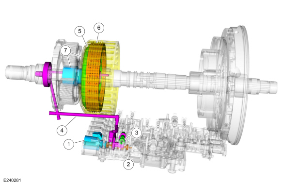
| Item | Description |
| 1 | SSE |
| 2 | E Clutch Control Valve |
| 3 | D Clutch Boost Control Valve |
| 4 | E Clutch Apply Circuit |
| 5 | E Clutch Piston |
| 6 | Clutch E Assembly |
| 7 | No. 4 Hub and Sun Gear |
Ring gear No. 3 is mechanically connected to sun gear No. 4, and both are connected to the E clutch. When the E clutch is applied, torque from the input shaft is transmitted to ring gear No. 3 and sun gear No. 4.
E Clutch Disassembled
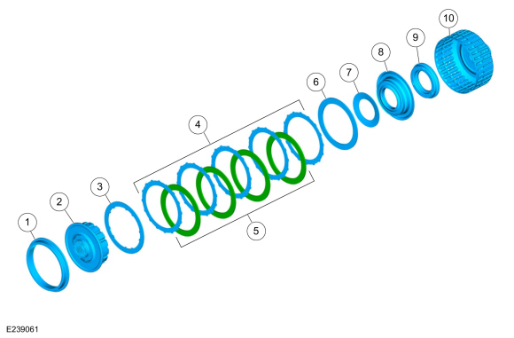
| Item | Description |
| 1 | No. 3 Ring Gear |
| 2 | E Clutch Hub |
| 3 | E Clutch Pressure Plate (Select Fit) |
| 4 | E Clutch Friction Plates (Quantity Varies by Model) |
| 5 | E Clutch Steel Plates (Quantity Varies by Model) |
| 6 | E Clutch Apply Plate (2.9-3.0 mm) |
| 7 | E Clutch Piston Return Spring |
| 8 | E Clutch Piston |
| 9 | E Clutch Balance Dam |
| 10 | No. 4 Hub and Sun Gear |
E Clutch Hydraulic Circuits
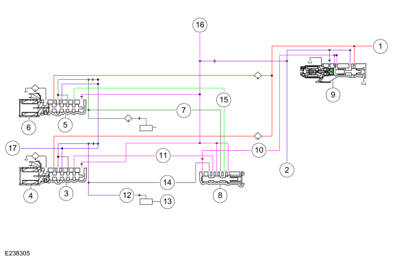
| Item | Description |
| 1 | Line Pressure |
| 2 | Pump Output |
| 3 | E Clutch Control Valve |
| 4 | SSE |
| 5 | D Clutch Control Valve |
| 6 | SSD |
| 7 | D Clutch supplies pressure to the clutch boost control valve |
| 8 | D Clutch Boost Control Valve |
| 9 | LPC Solenoid |
| 10 | Low Pressure |
| 11 | E Clutch Feedback Pressure |
| 12 | Supply Pressure to the E Mechanical Clutch |
| 13 | E Mechanical Clutch |
| 14 | E Clutch supplies pressure to the clutch boost control valve |
| 15 | D Clutch Feedback Pressure |
| 16 | Increased Exhaust Pressure |
| 17 | Clutch Exhaust |
E Clutch Hydraulic Apply 5-6 Shift
Line pressure is supplied to the E clutch control valve. LPC pressure is supplied to the boost control valve. LPC pressure positions the boost control valve at the right end of the valve bore. When SSE is energized, it moves the E clutch regulator valve, allowing regulated line pressure to flow to the E mechanical clutch.
E Clutch Hydraulic Apply 2-3, 4-5 and 9-10 Shifts
Line pressure is supplied to the E clutch control valve. LPC pressure is supplied to the boost control valve. LPC pressure is low, and the boost control valve remains in its default position at the left end of the valve bore. When SSE is energized, it moves the D clutch control valve, allowing regulated line pressure to flow to the E mechanical clutch.
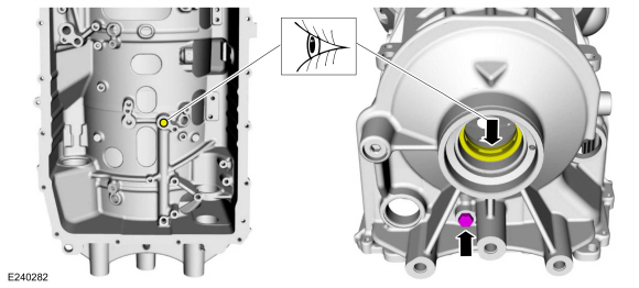
E Clutch Hydraulic Circuits
Test yourself
A quick Ford Explorer quiz: every answer comes with an explanation and a link to the manual page.