Diagnosis and Testing - Special Testing Procedures
Line Pressure Check
This test confirms that the line pressure is within specification.
- If available, refer to the General Procedure Transmission Line Pressure Check to access the line pressure tap.
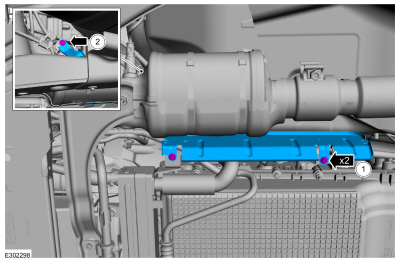
Refer to: Transmission Line Pressure Check (307-01A Automatic Transmission - 10-Speed Automatic Transmission - 10R60, General Procedures). - If equipped, remove the heat shield.
- Remove the 2 bolts. Torque: 10 N·m
- Remove the push pin and the heat shield.
- Connect the transmission fluid pressure gauge (307-004) to the line pressure test port using the M10 x 1.00 fitting.
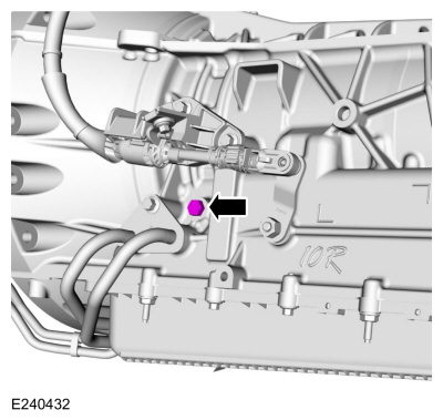
- Start the engine and check the line pressure.
- Using the diagnostic scan tool, monitor and compare the LINEDSD# PID with the actual measured pressure. The actual measured pressure should be within 10 psi (69 kPa) of the LINEDSD# PID. Raise engine speed to 2000 rpm and check LPC operation, monitoring line pressure while commanding LINEDSD# up and down.
- If the line pressure does not meet specification, refer to the Line Pressure Diagnosis Chart to determine possible causes.
- After completing the pressure tests, install the line pressure tap plug.
- Tighten to 11 N·m.
Line Pressure Diagnosis Chart
| Test Results | Possible Source |
| HIGH at idle |
|
| LOW at idle OR Does not change when commanding LINEDSD# up and down |
|
A no-drive condition may exist even with correct transmission fluid pressure due to non-functioning clutches. Refer to the Clutch Application Chart to determine which clutch is applied in each gear range. A clutch concern can be further diagnosed by performing the air pressure test.
Stall Speed Test
To prevent damage to transmission components, the PCM will reduce engine output torque when a stall condition exists. Due to this torque reduction, the stall test cannot be used as a diagnostic test to determine the condition of the transmission clutches.
The PCM monitors clutch operation and sets one or more DTCs when undesired slippage is detected.
The torque converter stator one-way clutch should hold during idle and during acceleration. A one-way clutch malfunction can be determined if all of the following conditions/symptoms are present:
- Transmission fluid is clean and not excessively contaminated
- Normal/expected vehicle performance at cruising speed
- Poor engine idle quality. The engine may even stall
- Very poor acceleration/lack of power
- Very low stall speed: <1500 rpm. Perform the test procedure below:
- Apply the parking brake.
- Connect the scan tool. Go to Data Logger: PCM
- Monitor PIDs: APP (%), RPM, LOAD (%) and GEAR_CMD.
- Start the engine.
- Select the Reverse gear range.
- Start the data logger recording.
- With the brake pedal firmly applied, depress the accelerator pedal to 100% for 2-3 seconds, until engine speed stabilizes. Release the accelerator pedal.
- Place the transmission in the Neutral position.
- Press the accelerator pedal to maintain 1500 rpm for 10 seconds to allow the torque converter to cool. Release the accelerator pedal.
- Shift into gear.
- With the brake pedal firmly applied, depress the accelerator pedal to 100% for 2-3 seconds, until engine speed stabilizes. Release the accelerator pedal.
- Place the transmission in the Neutral position.
- Press the accelerator pedal to maintain 1500 rpm for 10 seconds to allow the torque converter to cool. Release the accelerator pedal.
- Turn the engine off.
- Review the record. A properly functioning stator one-way clutch must meet the following specifications:
- APP = 100%
- RPM > 1500
- LOAD < 100%
- GEAR_CMD = Reverse or 1st gear command
Air Pressure Test
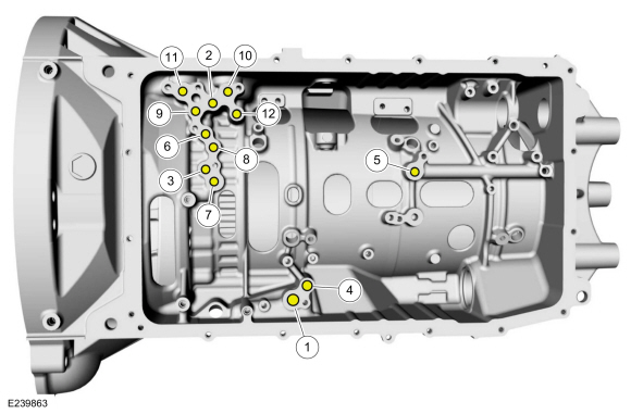
10R60/10R80 Air Ports
| Item | Description |
| 1 | Clutch |
| 2 | Clutch B |
| 3 | Clutch |
| 4 | Clutch D |
| 5 | Electric clutch |
| 6 | Clutch F |
| 7 | Apply TCC |
| 8 | Release TCC |
| 9 | Lube |
| 10 | Harder |
| 11 | From cooler |
| 12 | Line pressure tap |
- Using a high-volume air gun (3/8 inch diameter) with a rubber tip, apply 40 psi (276 kPa) to the suspect clutch port for 2-3 seconds.
- A thudding sound indicates clutch piston application.
- A hissing sound may indicate a leak in the hydraulic passages.
- Cross leaks between clutches C, D and F will be noticed if the air volume is insufficient to seat the Teflon seal rings.
- Holding the air gun nozzle firmly against the transmission case opening, release the trigger.
- Wait 1-2 seconds.
- A hissing sound may indicate a leak in the hydraulic passages.
- Remove the air gun from the port.
- A sudden release of air pressure indicates that the hydraulic passages are able to hold pressure.
- No sound may indicate a leak in the hydraulic passages.
Test yourself
A quick Ford Explorer quiz: every answer comes with an explanation and a link to the manual page.