Pinpoint Test - DTC: C. Diagnosis and Verification
In this manual: Body and Paint
~16min read
B0004:11, B0004:12, B0004:13 and B0004:1A
For circuit and connector information, refer to Wiring Diagrams Cell 46.
Normal Operation and Fault Symptoms
The RCM continuously monitors the driver lower airbag circuits for the following faults:
Resistance Out of Range
Unexpected Voltage
Short to Ground
Driver Lower Airbag Fault
When a fault is detected, the RCM stores DTC B0004:11, B0004:12, B0004:13 or B0004:1A in memory and sends a message to the IPC to illuminate the airbag indicator.
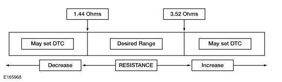
The RCM analyzes the deployment loop resistance to determine if a malfunction is present. The value displayed in the PID is the deployment loop resistance measured by the RCM. If the displayed value is below or above the desired range (see the chart below), the RCM may set a DTC. As the deployment loop resistance drifts further outside the desired range, the likelihood of a DTC setting increases. Small resistance fluctuations may occur due to the effect of road vibrations on the final seat belt connection. Crimps and terminals may be affected by stress and movement of the seat belt and may cause an increase in resistance due to wire tension. These variables may result in an intermittent fault. For this reason, the test requires the PID value to be within the desired range before the malfunction is considered repaired, regardless of whether the module reports the DTC on demand at the time of diagnosis. Following this direction helps ensure that minor resistance changes do not cause repeated concern. This test uses a process of elimination to diagnose each part of the deployment loop circuit, including:
Wiring
Connections
Driver Knee Airbag
RCM
DTC Fault Trigger Conditions
Trouble Code
Description
Fault Trigger Conditions
B0004:11
Driver Knee Airbag Deployment Control: short to ground
The fault is set when the RCM detects a short to ground in the circuit of either driver lower airbag for approximately 6 seconds.
B0004:12
Driver Knee Airbag Deployment Control: short to battery
The fault is set when the RCM detects a short to battery voltage in the circuit of either driver lower airbag for approximately 6 seconds.
B0004:13
Driver Knee Airbag Deployment Control: open circuit
The fault is set when the RCM measures a resistance greater than the desired range between the driver lower airbag circuits for approximately 6 seconds.
The fault is set when the RCM measures a resistance less than the desired range between the driver lower airbag circuits for approximately 6 seconds.
Possible Causes
Wiring, Terminals or Connectors
Driver Knee Airbag
RCM
Visual Inspection and Preliminary Diagnosis
Inspect the wiring harness for damage.
Inspect the connectors for loose or damaged terminals.
PINPOINT TEST A: B0004:11, B0004:12, B0004:13 AND B0004:1A
NOTE: Most concerns are related to connector and/or wiring issues. Perform a thorough inspection and check before proceeding to the Pinpoint Test.
NOTE: Only disconnect or reconnect SRS components when instructed to do so in the Pinpoint Test step. Failure to follow this instruction may result in an incorrect SRS diagnosis.
NOTE: Always verify the correct SRS component is installed. Parts released for other vehicles may be incompatible even if they appear physically similar. Check the part number listed in the Ford parts catalog to confirm the correct component is installed. If an incorrect SRS component is installed, diagnostic trouble codes (DTCs) may be set.
NOTE: Before returning the vehicle to the customer, the SRS must be fully functional and operating correctly.
A1 REMOVE RCM (RESTRAINTS CONTROL MODULE) DIAGNOSTIC TROUBLE CODES (DTCS)
WARNING: Before starting any service procedure in this section, refer to the Safety Warnings in Section 100-00 General Information. Failure to follow this instruction may result in serious personal injury. REFER TO: Pyrotechnic Device Handling Precautions (100-00 General Information, Description and Operation).
The ignition is on.
Using the diagnostic scanner, perform the RCM self-test.
Was DTC B0004:11, B0004:12, B0004:13 or B0004:1A retrieved on demand during the self-test?
Yes
This fault cannot be cleared until it is repaired and the DTC is no longer retrieved on demand during the self-test. For DTC B0004:13 or B0004:1A, GO to A2. For DTC B0004:11, GO to A8. For DTC B0004:12, GO to A10.
No
This is an intermittent fault if it is present only as a continuous memory diagnostic trouble code (CMDTC). For DTC B0004:13 or B0004:1A, GO to A13. For DTC B0004:11, GO to A14. For DTC B0004:12, GO to A15.
A2 CHECK THE DRIVER KNEE BOLSTER DEPLOYMENT CONTROL RESISTANCE (DEPLOY_02_R) PID (PARAMETER IDENTIFICATION)
Using the diagnostic scan tool, view the RCM parameter identification (PID) data.
Monitor and record the resistance value displayed by the DEPLOY_02_R PID.
Is the PID value between 1.44 and 3.52 Ohms?
Yes
GO to A12
No
GO to A3
A3 CHECK THE DRIVER KNEE AIRBAG DEPLOY CONTROL RESISTANCE (DEPLOY_02_R) PID (PARAMETER IDENTIFICATION) WHILE PERFORMING THE HARNESS CHECK
While monitoring the DEPLOY_02_R PID, perform a check of the driver lower airbag circuit harness and accessible connectors (including any integral connectors) by wiggling and frequently flexing the harness and connectors. Record the resistance value displayed by the PID.
Is the PID value within the range of 1.44 to 3.52 ohms during the harness check?
Yes
DISCONNECT the SRS from power and REPAIR the connector, terminals or harness as necessary. For wiring diagrams and connector information, refer to Wiring Diagrams, Cell 5. GO to A17
No
If the PID value is less than 1.44 ohms, GO to A4. If the PID value is greater than 3.52 ohms, GO to A6.
A4 CHECK THE DRIVER KNEE AIRBAG DEPLOY CONTROL DTC (DIAGNOSTIC TROUBLE CODE) FOR CHANGE IN FAULT STATUS (LOW RESISTANCE INDICATED)
Ignition OFF.
De-power the SRS. REFER to: Supplemental Restraint System (SRS) Disabling and Re-enabling (501-20B Supplemental Restraint System, General Procedures).
Remove the driver knee airbag. REFER TO: Driver Knee Airbag (501-20B Supplemental Restraint System, Removal and Installation).
Reset the SRS. Do not confirm the SRS at this time. Refer to: Supplemental Restraint System (SRS) Disabling and Re-enabling (501-20B Supplemental Restraint System, General Procedures).
The ignition is on.
Using the diagnostic scanner, perform the RCM self-test.
DIAGNOSTIC TIP: When viewing Diagnostic Trouble Codes (DTCs) with the driver knee airbag disconnected, an open circuit fault is typically eliminated.
Did the On-Demand DTC change from B0004:1A to B0004:13?
Yes
GO to A11
No
GO to A5
A5 CHECK FOR A SHORT BETWEEN THE DRIVER LOWER AIRBAG CIRCUITS
Ignition OFF.
De-power the SRS. REFER to: Supplemental Restraint System (SRS) Disabling and Re-enabling (501-20B Supplemental Restraint System, General Procedures).
Disconnect: RCM C310A and C310B.
Action: Click to display the connectors
Positive lead
Measurement/Action
Negative lead
C2432-1
C2432-2
Is the resistance greater than 10000 Ohms?
Yes
GO to A12
No
REPAIR the circuits. For wiring diagrams and connector information, refer to Wiring Diagrams, Cell 5. GO to A17
A6 CHECK THE DRIVER LOWER AIRBAG CIRCUITS FOR AN OPEN
Ignition OFF.
De-power the SRS. REFER to: Supplemental Restraint System (SRS) Disabling and Re-enabling (501-20B Supplemental Restraint System, General Procedures).
Remove the driver knee airbag. REFER TO: Driver Knee Airbag (501-20B Supplemental Restraint System, Removal and Installation).
Disconnect: RCM C310A and C310B.
Action: Click to display the connectors
Positive lead
Measurement/Action
Negative lead
C310A-11
C2432-1
C310A-12
C2432-2
Is the resistance less than 0.5 Ohms?
Yes
GO to A7
No
REPAIR the circuit(s). For wiring diagrams and connector information, refer to Wiring Diagrams, Cell 5. GO to A17
A7 CHECK THE DRIVER KNEE AIRBAG DEPLOY CONTROL DTC (DIAGNOSTIC TROUBLE CODE) FOR CHANGE IN FAULT STATUS (OPEN INDICATED)
Connect: RCM C310A and C310B.
Connect a fused jumper wire: Click to display connectors
Lead 1
Measurement/Action
Lead 2
C2432-1
C2432-2
Reset the SRS. Do not check the SRS at this time. REFER TO: Supplemental Restraint System (SRS) Disarming and Rearming (501-20B Supplemental Restraint System, General Procedures).
The ignition is on.
Using the diagnostic scanner, perform the RCM self-test.
DIAGNOSTIC TIP: When viewing Diagnostic Trouble Codes (DTCs) with the driver lower airbag circuits shorted together, a low resistance fault is typically restored.
Did the On-Demand DTC change from B0004:13 to B0004:1A?
Yes
REMOVE the fusible link and GO to A11.
No
REMOVE the fusible link and GO to A12.
A8 CHECK THE DRIVER KNEE AIRBAG DEPLOY CONTROL DTC (DIAGNOSTIC TROUBLE CODE) FOR CHANGE IN FAULT STATUS (SHORT TO GROUND INDICATED)
Ignition OFF.
De-power the SRS. REFER to: Supplemental Restraint System (SRS) Disabling and Re-enabling (501-20B Supplemental Restraint System, General Procedures).
Remove the driver knee airbag. REFER TO: Driver Knee Airbag (501-20B Supplemental Restraint System, Removal and Installation).
Reset the SRS. Do not check the SRS at this time. REFER TO: Supplemental Restraint System (SRS) Disarming and Rearming (501-20B Supplemental Restraint System, General Procedures).
The ignition is on.
Using the diagnostic scanner, perform the RCM self-test.
DIAGNOSTIC TIP: When viewing Diagnostic Trouble Codes (DTCs) with the driver knee airbag disconnected, an open circuit fault is typically eliminated.
Did the On-Demand DTC change from B0004:11 to B0004:13?
Yes
GO to A11
No
GO to A9
A9 CHECK THE DRIVER LOWER AIRBAG CIRCUITS FOR A SHORT TO GROUND
Ignition OFF.
De-power the SRS. REFER to: Supplemental Restraint System (SRS) Disabling and Re-enabling (501-20B Supplemental Restraint System, General Procedures).
Disconnect: RCM C310A and C310B.
Action: Click to display the connectors
Positive lead
Measurement/Action
Negative lead
C2432-1
Ground
C2432-2
Ground
Is the resistance greater than 10000 ohms?
Yes
GO to A12
No
REPAIR the circuit(s). For wiring diagrams and connector information, refer to Wiring Diagrams, Cell 5. GO to A17
A10 CHECK THE DRIVER LOWER AIRBAG CIRCUITS FOR A SHORT TO VOLTAGE
Ignition OFF.
De-power the SRS. REFER to: Supplemental Restraint System (SRS) Disabling and Re-enabling (501-20B Supplemental Restraint System, General Procedures).
Remove the driver knee airbag. REFER TO: Driver Knee Airbag (501-20B Supplemental Restraint System, Removal and Installation).
Disconnect: RCM C310A and C310B.
Reset the SRS. Do not check the SRS at this time. REFER TO: Supplemental Restraint System (SRS) Disarming and Rearming (501-20B Supplemental Restraint System, General Procedures).
The ignition is on.
Action: Click to display the connectors
Positive lead
Measurement/Action
Negative lead
C2432-1
Ground
C2432-2
Ground
Is there voltage present?
Yes
REPAIR the circuit(s). For wiring diagrams and connector information, refer to Wiring Diagrams, Cell 5. GO to A17
No
GO to A12
A11 CONFIRM THE DRIVER LOWER AIRBAG FAULT
Ignition OFF.
De-power the SRS. REFER to: Supplemental Restraint System (SRS) Disabling and Re-enabling (501-20B Supplemental Restraint System, General Procedures).
Before reconnecting any previously disconnected SRS component:
inspect the connector(s) (including any integral connectors) for pushed-out, loose or spread terminals, and loose or chafed wire connections at the terminals.
inspect the wiring harness for damage, pinching, or cut or pierced wires.
check the RCM C310A and C310B connector position assurance (CPA) lever/latch for proper operation.
repair any problems found. Refer to Wiring Diagrams Cell 5 for schematic and connector information.
Install the driver knee airbag. REFER TO: Driver Knee Airbag (501-20B Supplemental Restraint System, Removal and Installation).
Connect: RCM C310A and C310B.
Reset the SRS. Do not confirm the SRS at this time. Refer to: Supplemental Restraint System (SRS) Disabling and Re-enabling (501-20B Supplemental Restraint System, General Procedures).
The ignition is on.
Using the diagnostic scanner, perform the RCM self-test.
Was the original DTC retrieved on demand during the self-test?
Yes
INSTALL a new driver knee airbag. REFER TO: Driver Knee Airbag (501-20B Supplemental Restraint System, Removal and Installation). GO to A17
No
During the diagnosis, the condition became intermittent. Do not install new SRS components at this time. Install SRS components only when directed by the pinpoint test. For DTC B0004:13 or B0004:1A, GO to A13. For DTC B0004:11, GO to A14. For DTC B0004:12, GO to A15.
A12 CONFIRM THE RCM (RESTRAINTS CONTROL MODULE) FAULT
Ignition OFF.
Depower the SRS. REFER TO: Supplemental Restraint System (SRS) Re-enabling (501-20B Supplemental Restraint System, General Procedures).
Before reconnecting any previously disconnected SRS component:
inspect the connector(s) (including any integral connectors) for pushed-out, loose or spread terminals, and loose or chafed wire connections at the terminals.
inspect the wiring harness for damage, pinching, or cut or pierced wires.
check the RCM C310A and C310B connector position assurance (CPA) lever/latch for proper operation.
repair any problems found. Refer to Wiring Diagrams Cell 5 for schematic and connector information.
Install the driver knee airbag. REFER TO: Driver Knee Airbag (501-20B Supplemental Restraint System, Removal and Installation).
Connect: RCM C310A and C310B.
Reset the SRS. Do not check the SRS at this time. REFER TO: Supplemental Restraint System (SRS) Disarming and Rearming (501-20B Supplemental Restraint System, General Procedures).
The ignition is on.
Using the diagnostic scanner, perform the RCM self-test.
Was the original DTC retrieved on demand during the self-test?
Yes
CHECK OASIS for any applicable Technical Service Bulletins (TSBs). If a TSB exists for this concern, STOP this test and FOLLOW the TSB instructions. If no TSB applies to this concern, INSTALL a new RCM. REFER TO: Restraints Control Module (RCM) (501-20B Supplemental Restraint System, Removal and Installation). GO to A17
No
During the diagnosis, the condition became intermittent. Do not install new SRS components at this time. Install SRS components only when directed by the pinpoint test. For DTC B0004:13 or B0004:1A, GO to A13. For DTC B0004:11, GO to A14. For DTC B0004:12, GO to A15.
A13 CHECK THE DRIVER KNEE AIRBAG DEPLOY CONTROL RESISTANCE (DEPLOY_02_R) PID (PARAMETER IDENTIFICATION) FOR AN INTERMITTENT LOW RESISTANCE OR OPEN CIRCUIT
Using the diagnostic scan tool, view the RCM parameter identification (PID) data.
While monitoring the DEPLOY_02_R PID, attempt to duplicate the fault by wiggling the connectors (including any integral connectors) and frequently flexing the harness. Record the resistance value displayed by the PID.
Is the PID value between 1.44 and 3.52 Ohms?
Yes
The fault is not present and cannot be duplicated at this time. Do not install any new SRS components at this time. Install SRS components only when directed by the pinpoint test. GO to A16
No
DISCONNECT the SRS and REPAIR as necessary. For wiring diagrams and connector information, refer to Wiring Diagrams, Cell 5. GO to A17
A14 CHECK THE DRIVER KNEE AIRBAG DEPLOY CONTROL CIRCUITS FOR AN INTERMITTENT SHORT TO GROUND
Attempt to reproduce the fault by wiggling the connectors (including any inline connectors) and flexing the wiring harness frequently.
Using the diagnostic scanner, perform the RCM self-test.
Was DTC B0004:11 retrieved on-demand during the self-test?
Yes
DISCONNECT the SRS and REPAIR as necessary. For wiring diagrams and connector information, refer to Wiring Diagrams, Cell 5. GO to A17
No
The fault is not present and cannot be duplicated at this time. Do not install any new SRS components at this time. Install SRS components only when directed by the pinpoint test. GO to A16
A15 CHECK THE DRIVER KNEE AIRBAG DEPLOY CONTROL CIRCUITS FOR AN INTERMITTENT SHORT TO BATTERY
Ignition OFF.
De-power the SRS. REFER to: Supplemental Restraint System (SRS) Disabling and Re-enabling (501-20B Supplemental Restraint System, General Procedures).
Remove the driver knee airbag. REFER TO: Driver Knee Airbag (501-20B Supplemental Restraint System, Removal and Installation).
Reset the SRS. Do not check the SRS at this time. REFER TO: Supplemental Restraint System (SRS) Disarming and Rearming (501-20B Supplemental Restraint System, General Procedures).
The ignition is on.
Attempt to reproduce the fault by wiggling the connectors (including any inline connectors) and flexing the wiring harness frequently.
Using the diagnostic scanner, perform the RCM self-test.
Was DTC B0004:12 retrieved on demand during the self-test?
Yes
DISCONNECT the SRS and REPAIR as necessary. For wiring diagrams and connector information, refer to Wiring Diagrams, Cell 5. GO to A17
No
The fault is not present and cannot be duplicated at this time. Do not install any new SRS components at this time. Install SRS components only when directed by the pinpoint test. GO to A16
A16 CHECK THE HARNESS AND CONNECTORS
Ignition OFF.
De-power the SRS. REFER to: Supplemental Restraint System (SRS) Disabling and Re-enabling (501-20B Supplemental Restraint System, General Procedures).
Remove the driver knee airbag. REFER TO: Driver Knee Airbag (501-20B Supplemental Restraint System, Removal and Installation).
Inspect the connector(s) (including any inline connectors) for corrosion, loose or spread terminals, and loose or worn wire-to-terminal connections.
Inspect the wiring harness for damage, pinching, cut or pierced wires.
Inspect the RCM C310A and C310B connector position assurance (CPA) lever/latch for proper operation.
Were any concerns found?
Yes
REPAIR as necessary. For wiring diagrams and connector information, refer to Wiring Diagrams, Cell 5. GO to A17
No
The fault is not present and cannot be duplicated at this time. Do not install any new SRS components at this time. Install SRS components only when directed by the pinpoint test. GO to A17
A17 CHECK THE SUPPLEMENTAL RESTRAINT SYSTEM (SRS) DIAGNOSTIC TROUBLE CODES (DTCS)
Ignition OFF.
Remove the driver knee airbag (if previously removed). Refer to: Driver Knee Airbag (501-20B Supplemental Restraint System, Removal and Installation).
Reconnect all SRS components (if previously disconnected).
If previously instructed to disable the SRS, re-enable the SRS. Do not check the SRS at this time. Refer to: Supplemental Restraint System (SRS) Disabling and Arming (501-20B Supplemental Restraint System, General Procedures).
The ignition is on.
NOTE: When Restraints is selected in the Self Test menu, DTCs are retrieved from the RCM and OCSM. Using the diagnostic scanner, perform the Restraints Self Test.
Are any RCM and/or OCSM Diagnostic Trouble Codes (DTCs) retrieved on demand during the self-test?
Yes
Do not clear any Diagnostic Trouble Codes (DTCs) until all DTCs have been resolved. DIAGNOSE and REPAIR the RCM and/or OCSM DTCs. Refer to: Supplemental Restraint System (SRS) (501-20B).
No
CLEAR the Continuous Memory Diagnostic Trouble Codes (CMDTCs) in all modules. VERIFY the SRS. Repair is complete. RETURN the vehicle to the customer.
?
Test yourself
A quick Ford Fiesta quiz: every answer comes with an explanation and a link to the manual page.
 WARNING: Before starting any service procedure in this section, refer to the Safety Warnings in Section 100-00 General Information. Failure to follow this instruction may result in serious personal injury.


