Alternator - Inspection (75 A Model)
ROTOR
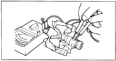
1. Check the rotor coil for an open circuit.
Check that there is continuity between the slip rings. If the resistance is too low (approaching 0), this indicates a short circuit. If the rotor coil is open or shorted, replace the rotor assembly. Resistance: approximately 3.1 ohms
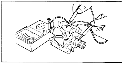
2. Check the rotor coil for a short to ground.
Check that there is no continuity between the slip ring and the core. If there is continuity (short to ground), replace the rotor assembly.
STATOR
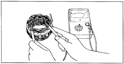
1. Check the stator coil for an open circuit.
Check for an open circuit between the stator winding terminals. If the winding circuit is open (resistance is infinite), replace the stator assembly.
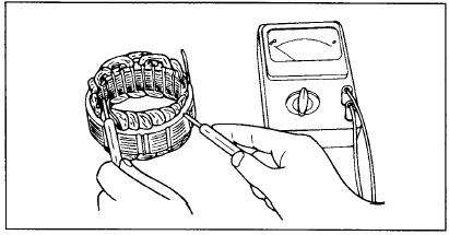
2. Check that the winding is not shorted to ground.
Check that the stator winding is not shorted to ground (there should be no continuity between the stator winding and the core). If the circuit is shorted (resistance approaches zero), replace the stator assembly.
CHECK POSITIVE RECTIFIER TERMINAL
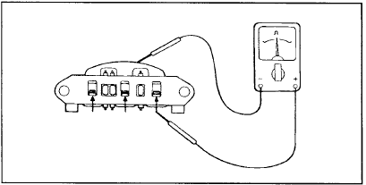
Using an ohmmeter, check that there is continuity (low resistance) between the positive diode terminal of the rectifier assembly and the stator winding terminal.
Reverse the ohmmeter probe connections and measure the resistance again. If resistance is low, i.e., there is continuity in both directions, the diode is punctured (shorted).
Replace the rectifier assembly.
CHECK NEGATIVE RECTIFIER TERMINAL
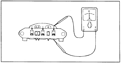
Using an ohmmeter, check that there is continuity (low resistance) between the negative diode terminal of the rectifier assembly and the stator winding terminal.
Reverse the ohmmeter probe connections and measure the resistance again. If resistance is low, i.e., there is continuity in both directions, the diode is punctured (shorted).
Replace the rectifier assembly.
CHECK THREE RECTIFIER DIODES
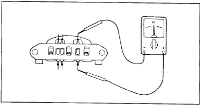
Check the three diodes by connecting the ohmmeter to both terminals of each diode. For each diode, there must be continuity in only one direction.
If there is no continuity in both directions, or if there is continuity in both directions, the diode is faulty and the rectifier (heat sink) assembly must be replaced.
BRUSH REPLACEMENT
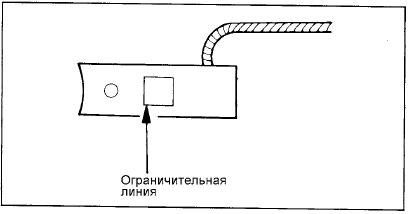
Replace the brushes if brush wear has reached the wear limit line.
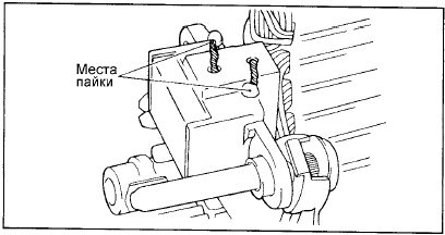
1. Unsolder the brush lead wire and remove the generator brush with spring.
2. Install the brush spring and new brush into the brush holder.
3. Insert the brush so that the distance between the edge of the brush holder and the wear limit line on the brush is 2 - 3 mm.
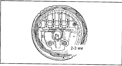
4. Solder the brush lead wire to the brush holder.
Test yourself
A quick Hyundai Elantra CN7 quiz: every answer comes with an explanation and a link to the manual page.