Charging System Inspection - Power Supply Circuit Inspection
The alternating magnetic field generated by the rotating alternator rotor induces an alternating EMF (alternating voltage) in the stator phase winding, varying in magnitude and direction.
INSPECTION PROCEDURE
1. Turn the ignition switch to the "ON" position.
2. Check that the battery charge warning light illuminates with the ignition on and the engine off.
3. Disconnect the field coil resistor connector.
Connect the ohmmeter probes to terminals 1 and 3 (on the resistor side). Connect the ohmmeter (+) lead to terminal 3 and the (-) lead to terminal 1.
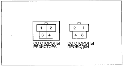
If the ohmmeter probes are connected incorrectly, the measurement results will be wrong. Make sure the probes are connected correctly and securely.
ANALYSIS OF RESULTS
1. If the circuit is continuous when the conditions of steps 2 and 3 are met, the circuit is normal.
If the circuit is open when the conditions of steps 2 and 3 are met, the circuit is faulty, but the battery is normal.
2. If the circuit is open only when the conditions of step 2 are met, check and repair the battery discharge warning lamp circuit.
If the circuit is open only when the conditions of step 3 are met, check and, if necessary, replace the field coil resistor. (Refer to the wiring diagram.)
If the circuit is open only under the conditions of one of the steps (2 or 3), the system will still function. However, repair the faulty circuit to ensure more reliable operation of the charging system.
Test yourself
A quick Hyundai Elantra CN7 quiz: every answer comes with an explanation and a link to the manual page.