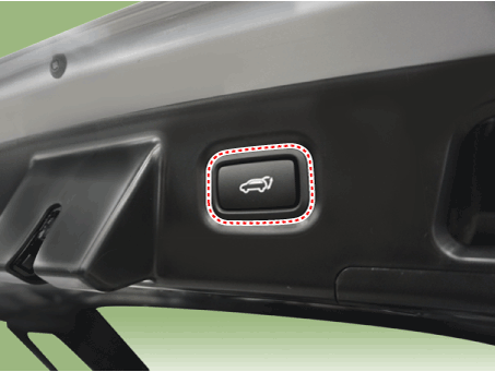
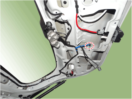
The power liftgate is an electromechanical system that provides powered opening and closing of the liftgate by pressing the button on the remote key fob, the console switch, the interior switch, or the switch on the outside handle of the liftgate. The power liftgate will reverse direction if resistance to movement is detected while the liftgate is opening or closing. Liftgate position and direction: The PTG system measures the liftgate position using a Hall-effect sensor built into the motor of the spindle drive unit. The direction of liftgate movement is determined by analyzing the direction of the drive unit motor. Hall sensor pulse counting (position detection) is active during power operation and manual operation. System components
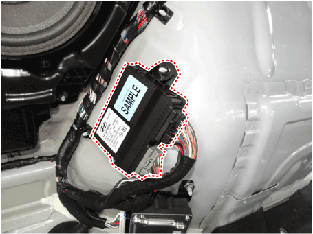
PTG moduleThe PTG module is located in the rear left side trim of the cargo area. The PTG drive unit operates the two actuators (spindles) by measuring the motors. The PTG module also controls the anti-pinch functions by analyzing the Hall sensor signal in the anti-pinch strip.
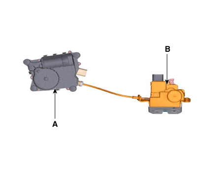
PTG latch assemblyThe PTG latch assembly consists of the power latch (A) and the power close unit (B). The power latch is located in the lower part of the liftgate panel.
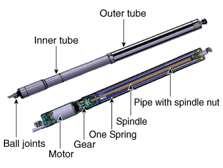
PTG spindleThe PTG spindle opens and closes the liftgate by driving the motor.
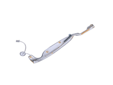
Anti-pinch stripDuring forced closing or latching, the PTG system must reverse to the open position if a signal is received from the anti-pinch strip. However, the anti-pinch strip will not operate when the liftgate is at standby in the fully closed, fully open, or closed positions.
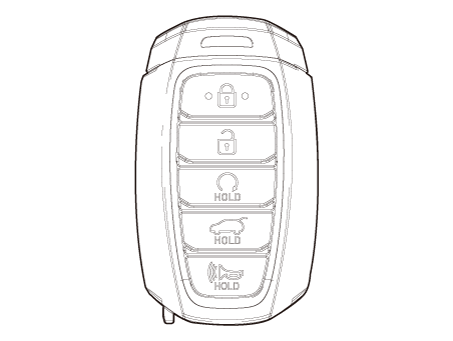
SMK (Smart Key)Press and hold the power liftgate button on the SMK for more than 0.5 s to power open the liftgate. The power open operation must be reversed when an additional open/close signal is received during opening/closing.
Liftgate interior switch
Liftgate buzzerWhen the power operation cannot be performed as requested or an obstacle has been detected.
Operation
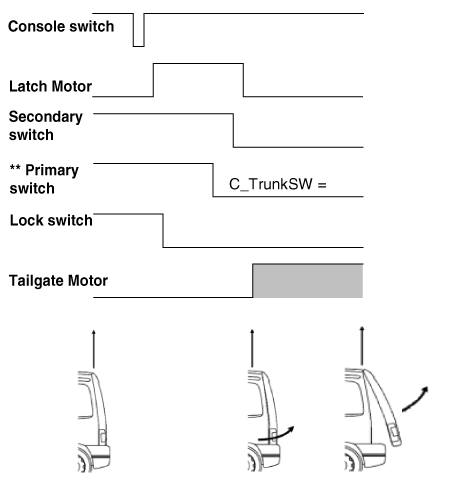
Power liftgate opening** - Primary switch signal received by PTGM via CAN bus (sent by SJB). PTGM opening procedure:
Opening can be initiated after receiving a signal from the console (driver) switch, the outside handle switch, or the remote key (FOB).
The latch will be released (SJB) when the latch motor operates.
When the latch is opened, the liftgate latch is extended out of the striker.
The PTG module controls the liftgate motor to open the liftgate.
The rotational speed of the liftgate motor can be determined by the Hall sensor built into the motor.
The liftgate opening angle is calculated by counting the input pulse signals from the Hall sensor.
When motor movement is restricted, the PTGM stops the liftgate motor movement due to obstacle detection.
Closing can be initiated after receiving a signal from the console (driver) switch, the outside handle switch, the remote key (FOB), or the interior switch.
The PTG module controls the liftgate motor to close the liftgate.
The liftgate closing angle is calculated by counting the input pulse signals from the Hall sensor.
The rotational speed of the liftgate motor can be determined by the Hall sensor built into the motor.
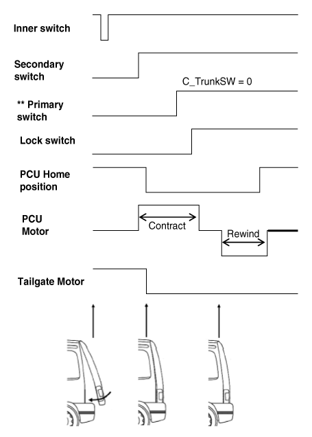
The liftgate latch engages with the striker and the latch locks mechanically (latch unlocked → latch locked).
The PTGM stops the liftgate motor operation after the liftgate secondary latch signal is detected.
When the secondary latch signal is detected, the power control unit (PCU) starts the latch operation (pull-in) and stops after the latch lock signal is detected.
After the latch operation stops, the PCU rewinds until the PCU returns to the home position.
The liftgate is fully closed and the latch is fully locked.
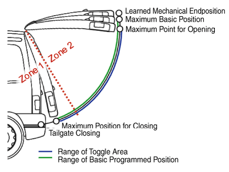
Maximum opening point: Starting movement in the opening direction above this position may cause the liftgate to move beyond the maximum base position and overload the mechanical system (hinges). Therefore, starting the opening action above this point is disabled. In any case, if the liftgate was started in a lower position, it will move beyond this point.
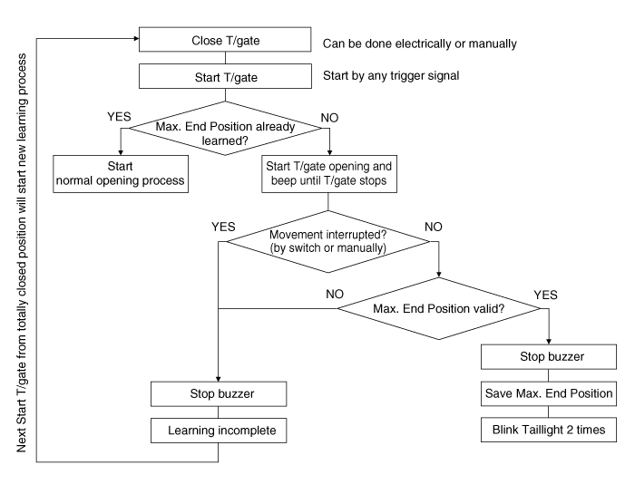
Learned mechanical end position: This is the position of the mechanical stop when opening and is considered to be 100% open. When the liftgate is first opened, this position is learned. After learning, the liftgate will not move beyond the maximum base position, which is determined by the learned mechanical position minus the safety distance. All positions are determined by parameters in the ECU or programmed by the user (base programmed position).
The programmed base position is customizable and is set equal to the maximum base position after the learned mechanical end position is learned.
The customer can change the programmed base position to any new position between the maximum closed position and the maximum base position.
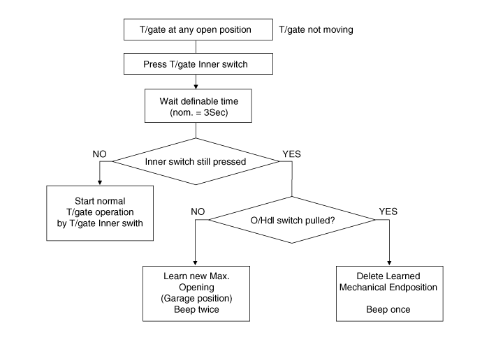
If the customer wants to set a new programmed base position lower than the current programmed base position, move the liftgate electrically or manually to the new position and press the interior switch for approx. 3 seconds (time can be changed by parameter).
If the customer wants to set a new programmed base position higher than the current programmed base position, move the liftgate manually to the new position and press the interior switch for 5 seconds (time can be changed by parameter).
If the user attempts to program the liftgate position above the maximum base position, the ECU will set the programmed base position to the maximum base position.
Power liftgate closing. PTGM closing procedure: Learned/calculated/programmed positions. Programming maximum liftgate opening (garage position). System parameterization: Due to mechanical tolerances and adjustments during vehicle manufacturing and assembly, the power liftgate must be calibrated to the maximum range of travel before proper operation is ensured. The maximum range of liftgate travel is represented by the number of Hall pulses received by the ECU from the drive position/speed sensors when the liftgate moves from the fully closed position (closing element in the fully closed position) to the upper end position limited by mechanical stops (e.g., stoppers, spindle length, etc.). Calibration mode. Manual decalibration mode. Buzzer operation is described in the following table.
BUZZER
LAMP *)
NOTE
T/Gate start
2 times
2 times
When T/Gate is operated by the remote transmitter or the console T/Gate switch
T/Gate start
N/A
N/A
When T/Gate is operated by the interior T/Gate switch or the exterior T/Gate handle switch
T/Gate stop
N/A
N/A
System error
3 times
-
PCU/liftgate backlash lock active, over-/under-voltage condition, end position/position error, spindle error, CAN error, latch closed when liftgate opened
T/Gate not closed
10 times
10 times
Latch switch missing
During calibration
Continuous chime ON-OFF
N/A
Activate buzzer, but not C_PTHazard
Max. end position learned
N/A
2 times
Buzzer confirms learning is complete
Max. end position deleted
1 time
N/A
Buzzer confirms "position deleted"
Vehicle moving with liftgate open
10 times
N/A
T/Gate open AND speed >3 km/h
Garage position stored
2 times
N/A
Buzzer confirms "New garage position"
*) The lamp will be synchronized by sending C_PTHazard to the buzzer at the same time as the signal.
?
Test yourself
A quick Hyundai Palisade quiz: every answer comes with an explanation and a link to the manual page.