Engine Control System/Fuel System
Description and Operation
In this manual: Engine Control System/Fuel System
9steps
~54min
2/5difficulty
Done 0 of 9
OBD-II Overview
1. Overview The California Air Resources Board (CARB) began regulating On-Board Diagnostics (OBD) for vehicles sold in California starting with the 1988 model year. The first stage, OBD-I, required monitoring of the fuel metering system, exhaust gas recirculation (EGR) system and additional emission-related components. The Malfunction Indicator Lamp (MIL) was required to illuminate and warn the driver of a malfunction and the need to repair the emission control system. Associated with the MIL was a trouble code or Diagnostic Trouble Code (DTC) identifying the specific area of the fault. The OBD system was proposed by CARB to improve air quality by identifying vehicles exceeding emission standards. The passage of the 1990 Clean Air Act Amendments also prompted the Environmental Protection Agency (EPA) to develop on-board diagnostic requirements. CARB OBD-II rules were followed until 1999, when federal standards were used. The OBD-II system complies with government standards by monitoring the emission control system. When a system or component exceeds the emission threshold or the component operates outside its tolerance, a DTC will be stored and the MIL will illuminate. The diagnostic executive is a computer program in the engine Control Module (ECM) or Powertrain Control Module (PCM) that coordinates the OBD-II self-check system. This program controls all monitors and interactions, the operation of DTCs and the MIL, freeze frame data and the scan tool interface. Freeze frame data describes the stored engine conditions, such as engine status, fuel control status, spark, speed, load and warm-up status at the moment the first malfunction is detected. Previously stored conditions will be replaced only when a fuel or misfire malfunction is detected. This data is available using a scan tool to assist in vehicle repair. The core of the OBD-II system is a microprocessor called the Engine Control Module (ECM) or Powertrain Control Module (PCM). The ECM or PCM receives data from sensors and other electronic components (switches, relays, etc.). Based on the information received and programmed into its memory (random access memory, etc.), the ECM or PCM generates output signals to control various relays, solenoids and actuators. 2. Hardware Configuration and Related Terms 1) GST (Generic Scan Tool)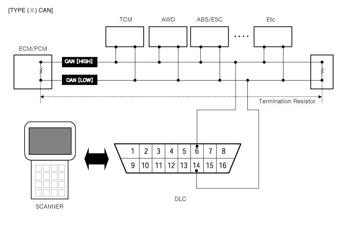
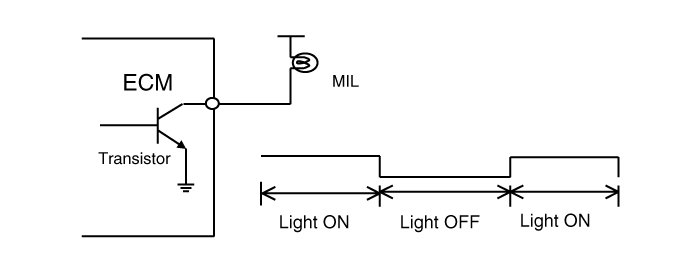
- Misfire and Fuel System Faults: For misfire or fuel system faults, the MIL may be turned off if the same fault is not detected during monitoring over three subsequent consecutive driving cycles in which conditions are similar to those under which the fault was first detected.
- All Other Faults: For all other faults, the MIL may be turned off after three subsequent consecutive driving cycles during which the monitoring system responsible for illuminating the MIL functions without detecting the fault, and provided no other fault has been detected that could illuminate the MIL independently under the requirements stated above.
- Bus Topology: Line (bus) structure
- Wiring: Twisted pair
- DLC External Cable Length: 5 m max.
- Data Transfer Rate
- Diagnostics: 500 kbps
- Service mode (reprogramming, VIN write): 500 kbps or 1 Mbps
- Diagnostic Trouble Code (SAE J2012)
- DTCs used in OBD-II vehicles begin with a letter followed by four digits.
- 1: Fuel and Air Metering
- 2: Fuel and Air Metering (injector circuit malfunction only)
- 3: Ignition System or Misfire
- 4: Auxiliary Emission Controls
- 5: Vehicle Speed Control and Idle Control System
- 6: Computer Output Circuits
- 7: Transmission
- Freeze Frame List
- Calculated Load Value
- Engine Speed
- Fuel Trim
- Fuel Pressure (if available)
- Vehicle Speed (if available)
- Engine Coolant Temperature
- Intake Manifold Pressure (if available)
- Closed Loop or Open Loop Operation
- Malfunction Code
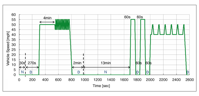
- Continental, Bosch or Kefico EMS: One Mode 1 driving cycle must be performed to diagnose all systems.
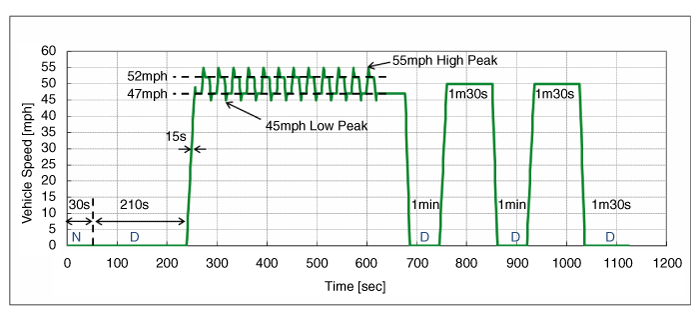
- Drive cycle for Mode 2 should be performed twice in a row. The series after Mode 1 is performed once for diagnosis on all systems.
- Mode 1
- Mode 2
| Mode | No | Operation | Speed (mph) |
Duration (s) |
E/Time (s) |
Notes |
| Mode 1 | 1 | Starting the Engine | 0 | 0 | 0 | ECT @ Start 32~104°F |
| 2 | Idle (N) | 0 | 30 | 30 | Neutral range | |
| 3 | Idle (D) | 0 | 270 | 300 | D Range | |
| 4 | Acceleration | 0 > 50 | 15 | 315 | ||
| 5 | Steady speed | 50 | 230 | 545 | ||
| 6 | Deceleration | 50 > 45 | 5 | 550 | ||
| 7 | Steady speed | 45 | 5 | 555 | ||
| 8 | Acceleration | 45 > 55 | 5 | 560 | ||
| 9 | Steady speed | 55 | 5 | 565 | ||
| 10 | Deceleration | 55 > 45 | 5 | 570 | ||
| 11 | Steady speed | 45 | 5 | 575 | ||
| 12 | Repeat steps 8 through 11 ten times. | - | 180 | 755 | ||
| 13 | Acceleration | 45 > 55 | 5 | 760 | ||
| 14 | Steady speed | 55 | 5 | 765 | ||
| 15 | Deceleration | 55 > 0 | 45 | 810 | ||
| 16 | Idle (D) | 0 | 120 | 930 | D Range | |
| 17 | Idle (N) | 0 | 760 | 1690 | Neutral range | |
| 18 | Acceleration | 0 > 55 | 15 | 1705 | ||
| 19 | Steady speed | 55 | 60 | 1765 | ||
| 20 | Deceleration | 55 > 0 | 15 | 1780 | ||
| 21 | Idle (D) | 0 | 60 | 1840 | D Range | |
| 22 | Acceleration | 0 > 55 | 15 | 1855 | ||
| 23 | Steady speed | 55 | 60 | 1915 | ||
| 24 | Deceleration | 55 > 0 | 15 | 1930 | ||
| 25 | Idle (D) | 0 | 60 | 1990 | D Range | |
| 26 | Acceleration | 0 > 40 | 15 | 2005 | ||
| 27 | Steady speed | 40 | 15 | 2020 | ||
| 28 | Acceleration | 40 > 50 | 15 | 2035 | ||
| 29 | Steady speed | 50 | 5 | 2040 | ||
| 30 | Deceleration | 50 > 40 | 15 | 2055 | ||
| 31 | Steady speed | 40 | 60 | 2115 | ||
| 32 | Repeat steps 28 through 31 five times. | - | 380 | 2495 | ||
| 33 | Acceleration | 40 > 50 | 15 | 2510 | ||
| 34 | Steady speed | 50 | 5 | 2515 | ||
| Mode 1 | 35 | Deceleration | 50 > 0 | 40 | 2555 | |
| 36 | Idle (D) | 0 | 25 | 2580 | D Range | |
| Mode 2 | 1 | Starting the Engine | 0 | 0 | 0 | |
| 2 | Idle (N) | 0 | 30 | 30 | Neutral range | |
| 3 | Idle (D) | 0 | 210 | 240 | D Range | |
| 4 | Acceleration | 0 > 49 | 16 | 256 | ||
| 5 | Deceleration | 49 > 47 | 2 | 258 | Lift foot off pedal: APS = 0 | |
| 6 | Steady speed | 47 | 10 | 268 | ||
| 7 | Acceleration | 47 > 55 | 4 | 272 | Medium tip or wide-open throttle acceleration | |
| 8 | Deceleration | 55 > 52 | 3 | 275 | Lift foot off pedal: APS = 0 | |
| 9 | Steady speed | 52 | 10 | 285 | ||
| 10 | Deceleration | 52 > 45 | 3 | 288 | Lift foot off pedal: APS = 0 | |
| 11 | Acceleration | 45 > 47 | 2 | 290 | ||
| 12 | Repeat steps 6 through 11 twelve times. | - | 330 | 620 | ||
| 13 | Steady speed | 47 | 57 | 677 | ||
| 14 | Deceleration | 47 > 0 | 8 | 685 | ||
| 15 | Idle (D) | 0 | 60 | 745 | D Range | |
| 16 | Acceleration | 0 > 50 | 15 | 760 | ||
| 17 | Steady speed | 50 | 90 | 850 | ||
| 18 | Deceleration | 50 > 0 | 10 | 860 | ||
| 19 | Repeat steps 15 through 18 twice. | - | 175 | 1035 | ||
| 20 | Idle (D) | 0 | 90 | 1125 | D Range |
1) Catalyst Monitor The catalyst efficiency monitor is a self-diagnostic strategy in the ECM or PCM that uses the downstream heated oxygen sensor (HO2S) to determine when the catalytic converter has dropped below the minimum efficiency level in its ability to control exhaust emissions. 2) Misfire Monitor Misfires are defined as the lack of proper combustion in a cylinder due to lack of spark, poor fuel metering, or poor compression. Any combustion that occurs outside the cylinder at the correct time is also a misfire. The misfire detection monitor detects fuel, ignition, or mechanical misfires. The purpose is to protect the catalyst from irreversible damage and to alert the customer of an emissions failure or service failure by illuminating the MIL. When a misfire is detected, special software called "freeze frame" data is activated. Freeze frame data captures the vehicle operating condition when a misfire detection fault occurs. 3) Fuel System Monitor The fuel system monitor is a self-diagnostic strategy within the ECM or PCM that monitors the adaptive fuel table. The fuel control system uses an adaptive fuel table to compensate for normal variability of fuel system components caused by wear or aging. During normal vehicle operation, if the fuel system operates lean or rich, the adaptive value table will shift fuel delivery calculations to remove the bias. 4) Engine Cooling System Monitor The cooling system monitor is a self-diagnostic strategy in the ECM or PCM that monitors the ECT (Engine Coolant Temperature) sensor and thermostat for circuit continuity, range/performance, and rationality faults. 5) O2 Sensor Monitor OBD-II regulations require monitoring of the O2 sensor (HO2S) to detect sensor deterioration that exceeds threshold values. The additional oxygen sensor is located downstream of the Warm-Up Three-Way Catalytic Converter (WU-TWC) to determine catalyst efficiency. Although the downstream HO2S is similar in type to the one used for fuel control, it operates differently. The downstream HO2S is monitored to determine whether voltage is generated. This voltage is compared with the calibrated permissible range. 6) EVAP System Monitor The EVAP monitor is a self-diagnostic strategy within the ECM or PCM that checks the integrity of the EVAP system. The complete evaporative system detects leaks or total leaks equal to or greater than a leak caused by a 0.040 inch and a 0.020 inch diameter orifice. 7) Air Conditioning System Monitor The air conditioning system monitor is a self-diagnostic strategy within the ECM or PCM that monitors the malfunction of all air conditioning system components. N/A. 8) Comprehensive Component Monitor The comprehensive component monitor is a self-diagnostic strategy in the ECM or PCM that detects a malfunction of any electronic component or transmission system that provides input to the ECM or PCM and is not exclusively an input for any other OBD-II monitor. 9) Air Conditioning Component Monitoring Requirement: If the vehicle includes an engine control strategy that disables fuel and/or spark control at idle when the air conditioning system is on, the OBD II system must monitor all electronic air conditioning components for malfunctions that prevent the system from making the alternative control when the air conditioning system is on, or cause the system to make the alternative control when the air conditioning system is off. In addition, the OBD II system must monitor for malfunctions of all electronic air conditioning components that are used as part of the diagnostic strategy for any other monitored system or component. Implementation Plan: No engine control strategy is included that changes the idle position of fuel and/or spark control with the air conditioning on. Air conditioning system component malfunctions are not used as part of the diagnostic strategy for another monitored system or component.
Test yourself
A quick Hyundai Tucson LM quiz: every answer comes with an explanation and a link to the manual page.
Was this page helpful?