Engine Control System/Fuel System
Engine Control Module (ECM) Circuit Diagrams
In this manual: Engine Control System/Fuel System
~35min read
ECM Terminal and Input/Output Signal [M/T]
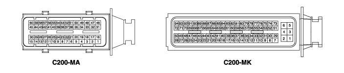
ECM Terminal Function (M/T)
Connector [C200-MA]| Pin No. | Description | Connected To |
| 1 | Injector (Cylinder No. 3) [High] Control Output | Injector (Cylinder #3) |
| 2 | Injector (Cylinder No. 4) [High] Control Output | Injector (Cylinder No. 4) |
| 3 | Injector (Cylinder No. 2) [Low] Control Output | Injector (Cylinder #2) |
| 4 | - | X |
| 5 | Heated Oxygen Sensor (HO2S) [Bank 1 / Sensor 1] Heater Control Output | Heated Oxygen Sensor (HO2S) [Bank 1/Sensor 1] |
| 6 | - | X |
| 7 | Cruise Control Power | Cruise control switch |
| 8 | - | X |
| 9 | - | X |
| 10 | - | X |
| 11 | - | X |
| 12 | Immobilizer Lamp Control Output | Cluster |
| 13 | - | |
| 14 | Cooling Fan Relay [High] Control Output | Cooling Fan Relay [High] |
| 15 | CVVT Oil Control Valve (OCV) Control Output [Bank 1/Exhaust] | CVVT Oil Control Valve (OCV) [Bank 1/Exhaust] |
| 16 | Injector (Cylinder No. 2) [High] Control Output | Injector (Cylinder #2) |
| 17 | Injector (Cylinder No. 1) [High] Control Output | Injector (Cylinder No. 1) |
| 18 | Injector (Cylinder No. 3) [Low] Control Output | Injector (Cylinder #3) |
| 19 | - | X |
| 20 | Heated Oxygen Sensor (HO2S) [Bank 1 / Sensor 2] Heater Control Output | Heated Oxygen Sensor (HO2S) [Bank 1/Sensor 2] |
| 21 | - | X |
| 22 | - | X |
| 23 | Engine Coolant Temperature Sensor (ECTS) Signal Input | Engine Coolant Temperature Sensor (ECTS)x |
| 24 | Sensor Ground | Engine Coolant Temperature Sensor (ECTS) |
| 25 | - | X |
| 26 | Fuel Tank Pressure Sensor (FTPS) Signal Input | Fuel Tank Pressure Sensor (FTPS) |
| 27 | Fuel Pump Relay Control Output (without Immobilizer) | Fuel Pump Relay |
| Canister Closure Valve (CCV) Control Output (with Immobilizer) | Canister Close Valve (CCV) | |
| 28 | - | X |
| 29 | A/C Compressor Relay Control Output | A/C Compressor Relay |
| 30 | - | X |
| 31 | Ignition Coil Control Output (Cylinder #3) | Ignition Coil (Cylinder No. 3) |
| 32 | Ignition Coil Control Output (Cylinder No. 1) | Ignition Coil (Cylinder No. 1) |
| 33 | Injector (Cylinder No. 1) [Low] Control Output | Injector (Cylinder No. 1) |
| 34 | Fuel Pressure Control Valve (FPCV) [High] Control Output | Fuel Pressure Control Valve (FPCV) |
| 35 | ETC Motor [-] Control Output | ETC motor |
| 36 | - | X |
| 37 | Knock Sensor (KS) Signal Input | Knock Sensor (KS) |
| 38 | Sensor Ground | Knock Sensor (KS) |
| 39 | - | |
| 40 | Stop Lamp Switch Input Signal | Brake Switch |
| 41 | - | |
| 42 | - | |
| 43 | - | X |
| 44 | - | X |
| 45 | CVVT Oil Control Valve (OCV) [Bank 1/Intake] Control Output | CVVT Oil Control Valve (OCV) [Bank 1/Intake] |
| 46 | Ignition Coil Control Output (Cylinder No. 4) | Ignition Coil (Cylinder No. 4) |
| 47 | Ignition Coil Control Output (Cylinder #2) | Ignition Coil (Cylinder No. 2) |
| 48 | Injector (Cylinder No. 4) [Low] Control Output | Injector (Cylinder No. 4) |
| 49 | Fuel Pressure Control Valve (FPCV) [Low] Control Output | Fuel Pressure Control Valve (FPCV) |
| 50 | ETC Motor [+] Control Output | ETC motor |
| 51 | - | |
| 52 | - | X |
| 53 | Brake Switch Signal Input | Brake Switch |
| 54 | - | |
| 55 | Clutch Switch Signal Input | Clutch Switch |
| 56 | - | |
| 57 | Generator COM Signal Output | Generator |
| 58 | Engine Speed Output Signal | Smart Key Control Module |
| 59 | Cooling Fan Relay [Low] Control Output | Cooling Fan Relay |
| 60 | Variable Intake Solenoid (VIS) Valve Control Output | Variable Intake Solenoid (VIS) |
Connector [C200-MK]
| Pin No. | Description | Connected To |
| 1 | ECM Ground | Ground |
| 2 | ECM Ground | Ground |
| 3 | ECM Ground | Ground |
| 4 | Battery Power (B+) | Main Relay |
| 5 | Battery Power (B+) | Battery |
| 6 | Battery Power (B+) | Battery |
| 7 | Battery Power (B+) | Main Relay |
| 8 | Sensor Ground | Heated Oxygen Sensor (HO2S) [Bank 1 / Sensor 2] |
| 9 | Accelerator Pedal Position Sensor (APS) 1 Signal Input | Accelerator Pedal Position Sensor (APS) 1 |
| 10 | Sensor Ground | Accelerator Pedal Position Sensor (APS) 2 |
| 11 | - | X |
| 12 | Sensor Ground | Fuel Tank Pressure Sensor (FTPS) |
| 13 | - | X |
| 14 | Throttle Position Sensor (TPS) 1 Signal Input | Throttle Position Sensor (TPS) 1 |
| 15 | - | X |
| 16 | - | X |
| 17 | Fuel Level Input Signal | Fuel Level Sensor (FLS) |
| 18 | Sensor Power Supply (+5V) | Accelerator Pedal Position Sensor (APS) 2 |
| 19 | - | X |
| 20 | Sensor Power Supply (+5V) | Rail Pressure Sensor (RPS) |
| Air Conditioning Pressure Sensor (APT) | ||
| 21 | - | X |
| 22 | - | |
| 23 | - | |
| 24 | Generator PWM Signal Output | Generator |
| 25 | - | X |
| 26 | - | X |
| 27 | - | X |
| 28 | - | X |
| 29 | Ignition Switch Input Signal | X |
| 30 | Heated Oxygen Sensor (HO2S) [Bank 1 / Sensor 2] Signal Input | Heated Oxygen Sensor (HO2S) [Bank 1 / Sensor 2] |
| 31 | Accelerator Pedal Position Sensor (APS) 2 Signal Input | Accelerator Pedal Position Sensor (APS) 2 |
| 32 | Sensor Ground | Accelerator Pedal Position Sensor (APS) 1 |
| 33 | - | X |
| 34 | - | X |
| 35 | Sensor Ground | Throttle Position Sensor (TPS) |
| 36 | Throttle Position Sensor (TPS) 2 Signal Input | Throttle Position Sensor (TPS) 2 |
| 37 | - | X |
| 38 | - | X |
| 39 | Sensor Power Supply (+5V) | Throttle Position Sensor (TPS) 1,2 |
| 40 | Sensor Power Supply (+5V) | Accelerator Pedal Position Sensor (APS) 1 |
| 41 | Sensor Power Supply (+5V) | Manifold Absolute Pressure Sensor (MAPS) |
| Fuel Tank Pressure Sensor (FTPS) | ||
| 42 | - | |
| 43 | - | |
| 44 | - | |
| 45 | Air Conditioning Pressure Sensor (APT) Signal Input | Air Conditioning Pressure Sensor (APT) |
| 46 | Vehicle Speed Signal Input | Vehicle speed sensor |
| 47 | - | |
| 48 | - | X |
| 49 | - | X |
| 50 | Malfunction Indicator Lamp (MIL) Control Output | Malfunction Indicator Lamp (MIL) |
| 51 | - | X |
| 52 | VS-/IP- (Common Ground for VS, IP) | Heated Oxygen Sensor (HO2S) [Bank 1/Sensor 1] |
| 53 | Rc/Rp (Pump Cell Voltage) | Heated Oxygen Sensor (HO2S) [Bank 1/Sensor 1] |
| 54 | - | X |
| 55 | - | X |
| 56 | Cruise Control Switch Ground | Cruise control switch |
| 57 | - | X |
| 58 | Rail Pressure Sensor (RPS) Signal Input | Rail Pressure Sensor (RPS) |
| 59 | Cruise Control Switch Signal Input | Cruise control switch |
| 60 | Start Signal Input | PDM Module |
| 61 | LIN Communication Input Signal | Battery Sensor |
| 62 | CCP-CAN [Low] | Other Control Module, Data Link Connector (DLC), Multi-Purpose Check Connector |
| 63 | CAN [Low] | Other Control Module, Data Link Connector (DLC), Multi-Purpose Check Connector |
| 64 | Sensor Ground | Camshaft Position Sensor (CMPS) [Bank 1 / Exhaust] |
| 65 | Camshaft Position Sensor (CMPS) [Bank 1 / Exhaust] Input Signal | Camshaft Position Sensor (CMPS) [Bank 1 / Exhaust] |
| 66 | - | X |
| 67 | Crankshaft Position Sensor (CKPS) [B] Signal Input | Crankshaft Position Sensor (CKPS) |
| 68 | - | X |
| 69 | - | X |
| 70 | - | X |
| 71 | - | X |
| 72 | Purge Control Solenoid Valve (PCSV) Control Output | Purge Control Solenoid Valve (PCSV) |
| 73 | - | X |
| 74 | VS+ (Nernst Cell Voltage) | Heated Oxygen Sensor (HO2S) [Bank 1/Sensor 1] |
| 75 | Rc (Compensation Resistance) | Heated Oxygen Sensor (HO2S) [Bank 1/Sensor 1] |
| 76 | Sensor Ground | Rail Pressure Sensor (RPS) |
| 77 | Sensor Ground | Air Conditioning Pressure Sensor (APT) |
| 78 | Sensor Ground | Manifold Absolute Pressure Sensor (MAPS) |
| 79 | Intake Air Temperature Sensor (IATS) Input Signal | Intake Air Temperature Sensor (IATS) |
| 80 | Manifold Absolute Pressure Sensor (MAPS) Signal Input | Manifold Absolute Pressure Sensor (MAPS) |
| 81 | - | X |
| 82 | - | X |
| 83 | Immobilizer Communication Line | Smart Key Control Module [with Engine Start Button] |
| Immobilizer Control Module [without Engine Start Button] | ||
| 84 | - | X |
| 85 | CAN [High] | Other Control Module, Data Link Connector (DLC), Multi-Purpose Check Connector |
| 86 | Sensor Ground | Camshaft Position Sensor (CMPS) [Bank 1 / Intake] |
| 87 | Camshaft Position Sensor (CMPS) [Bank 1/Intake] Signal Input | Camshaft Position Sensor (CMPS) [Bank 1 / Intake] |
| 88 | - | |
| 89 | Crankshaft Position Sensor (CKPS) Input Signal [A] | Crankshaft Position Sensor (CKPS) |
| 90 | Canister Closure Valve (CCV) Control Output (without Immobilizer) | Canister Close Valve (CCV) |
| Fuel Pump Relay Control Output (with Immobilizer) | Fuel Pump Relay | |
| 91 | - | X |
| 92 | - | X |
| 93 | Main Relay Control Output | Main Relay |
| 94 | Starter Relay (Low) Control Output | Starter Relay |
ECM Terminal Input/Output Signal (M/T)
Connector [C200-MA]| Pin No. | Description | Condition | Type | Level |
| 1 | Injector (Cylinder No. 3) [High] Control Output | Relay ON/OFF | DC Voltage | 71 V |
| 2 | Injector (Cylinder No. 4) [High] Control Output | Relay ON/OFF | DC Voltage | 71 V |
| 3 | Injector (Cylinder No. 2) [Low] Control Output | Relay OFF | DC Voltage | 71 V |
| Relay ON | Max. 1.0 V | |||
| 4 | - | X | X | X |
| 5 | Heated Oxygen Sensor (HO2S) [Bank 1 / Sensor 1] Heater Control Output | Relay OFF | DC Voltage | Battery Voltage |
| Relay ON | Max. 1.65 V | |||
| 6 | - | X | X | X |
| 7 | Power supply (+5V) | X | X | X |
| 8 | - | X | X | X |
| 9 | - | X | X | X |
| 10 | - | X | X | X |
| 11 | - | X | X | X |
| 12 | Immobilizer Indicator Lamp Control Output | X | X | X |
| 13 | - | X | X | X |
| 14 | Cooling Fan Relay [High] Control Output | Relay OFF | DC Voltage | Battery Voltage |
| Relay ON | Max. 1.76 V | |||
| 15 | CVVT Oil Control Valve (OCV) Control Output [Bank 1/Exhaust] | Idle | Pulse | High: Battery voltage |
| Low: Max. 1.65 V | ||||
| 16 | Injector (Cylinder No. 2) [High] Control Output | Relay ON/OFF | DC Voltage | 71 V |
| 17 | Injector (Cylinder No. 1) [High] Control Output | Relay ON/OFF | DC Voltage | 71 V |
| 18 | Injector (Cylinder No. 3) [Low] Control Output | Relay OFF | DC Voltage | 71 V |
| Relay ON | Max. 1.0 V | |||
| 19 | - | X | X | X |
| 20 | Heated Oxygen Sensor (HO2S) [Bank 1 / Sensor 2] Heater Control Output | Relay OFF | DC Voltage | Battery Voltage |
| Relay ON | Max. 1.65 V | |||
| 21 | - | X | X | X |
| 22 | - | X | X | X |
| 23 | Engine Coolant Temperature Sensor (ECTS) Signal Input | Idle | Analog | 0.270 ~ 4.77 V |
| 24 | Sensor Ground | Idle | DC Voltage | Max. 50 mV |
| 25 | - | X | X | X |
| 26 | Fuel Tank Pressure Sensor (FTPS) Signal Input | Idle | Analog | 0.3343 ~ 0.4667 V |
| 27 | Canister Closure Valve (CCV) Control Output (with Immobilizer) | Active | DC Voltage | Battery Voltage |
| Inactive | Max. 1.76 V | |||
| Fuel Pump Relay Control Output (without Immobilizer) | Relay OFF | DC Voltage | Battery Voltage | |
| Relay ON | Max. 1.44 V | |||
| 28 | - | X | X | X |
| 29 | A/C Compressor Relay Control Output | Relay OFF | DC Voltage | Battery Voltage |
| Relay ON | Max. 1.0 V | |||
| 30 | - | X | X | X |
| 31 | Ignition Coil Control Output (Cylinder #3) | Idle | Pulse | 1st Voltage: 370 ~ 430 V |
| ON Voltage: 2.2 V Max. | ||||
| 32 | Ignition Coil Control Output (Cylinder No. 1) | Idle | Pulse | 1st Voltage: 370 ~ 430 V |
| ON Voltage: 2.2 V Max. | ||||
| 33 | Injector (Cylinder No. 1) [Low] Control Output | Relay OFF | DC Voltage | 71 V |
| Relay ON | Max. 1.0 V | |||
| 34 | Fuel Pressure Control Valve (FPCV) [High] Control Output | Relay ON/OFF | DC Voltage | 16 V |
| 35 | ETC Motor [-] Control Output | Idle | Pulse | High: Battery voltage |
| Low: Max. 1.0 V | ||||
| 36 | - | X | X | X |
| 37 | Knock Sensor (KS) Signal Input | Knock | Variable | X |
| Normal | Frequency | X | ||
| 38 | Sensor Ground | Knock | Variable | X |
| Normal | Frequency | X | ||
| 39 | Fan Switch Max. Signal Input | X | X | X |
| 40 | Stop Lamp Switch Input Signal | ON | DC Voltage | Battery Voltage |
| OFF | Max. 2.25 V | |||
| 41 | Wheel Speed Sensor Signal Input [B] [Without ABS/ESC] | X | X | X |
| 42 | Wheel Speed Sensor Signal Input [A] [Without ABS/ESC] | X | X | X |
| 43 | - | X | X | X |
| 44 | - | X | X | X |
| 45 | CVVT Oil Control Valve (OCV) [Bank 1/Intake] Control Output | Idle | Pulse | High: Battery voltage |
| Low: Max. 1.65 V | ||||
| 46 | Ignition Coil Control Output (Cylinder No. 4) | Idle | Pulse | 1st Voltage: 370 ~ 430 V |
| ON Voltage: 2.2 V Max. | ||||
| 47 | Ignition Coil Control Output (Cylinder #2) | Idle | Pulse | 1st Voltage: 370 ~ 430 V |
| ON Voltage: 2.2 V Max. | ||||
| 48 | Injector (Cylinder No. 4) [Low] Control Output | Relay OFF | DC Voltage | 71 V |
| Relay ON | Max. 1.0 V | |||
| 49 | Fuel Pressure Control Valve (FPCV) [Low] Control Output | Relay OFF | DC Voltage | 16 V |
| Relay ON | Max. 1.0 V | |||
| 50 | ETC Motor [+] Control Output | Idle | Pulse | High: Battery voltage |
| Low: Max. 1.0 V | ||||
| 51 | - | |||
| 52 | - | X | X | X |
| 53 | Brake Switch Signal Input | ON | DC Voltage | Battery Voltage |
| OFF | Max. 2.25 V | |||
| 54 | Heated Oxygen Sensor (HO2S) [Bank 1 / Sensor 1] Signal Input | Engine | Analog | Rich: 0.6 ~ 1.0 V |
| Run | Ground: Max. 0.4 V | |||
| 55 | Clutch Switch Signal Input | X | X | X |
| 56 | - | |||
| 57 | Generator COM Signal Output | Idle | Pulse | High: Battery voltage |
| Low: Max. 0.6 V | ||||
| 58 | Engine Speed Output Signal | |||
| 59 | Cooling Fan Relay [Low] Control Output | Relay OFF | DC Voltage | Battery Voltage |
| Relay ON | Max. 1.76 V | |||
| 60 | Variable Intake Solenoid (VIS) Valve Control Output | Relay OFF | DC Voltage | Battery Voltage |
| Relay ON | Max. 1.65 V |
Connector [C200-MK]
| Pin No. | Description | Condition | Type | Level |
| 1 | ECM Ground | Idle | DC Voltage | Max. 50 mV |
| 2 | ECM Ground | Idle | DC Voltage | Max. 50 mV |
| 3 | ECM Ground | Idle | DC Voltage | Max. 50 mV |
| 4 | Battery Power (B+) | IG OFF | DC Voltage | Max. 1.0 V |
| IGNITION ON | Battery Voltage | |||
| 5 | Battery Power (B+) | IG OFF | DC Voltage | Max. 1.0 V |
| IGNITION ON | Battery Voltage | |||
| 6 | Battery Power (B+) | IG OFF | DC Voltage | Max. 1.0 V |
| IGNITION ON | Battery Voltage | |||
| 7 | Battery Power (B+) | IG OFF | DC Voltage | Max. 1.0 V |
| IGNITION ON | Battery Voltage | |||
| 8 | Sensor Ground | Idle | DC Voltage | Max. 50 mV |
| 9 | Accelerator Pedal Position Sensor (APS) 1 Signal Input | Idle | Analog | 0.674 ~ 4.379 V |
| 10 | Sensor Ground | Idle | DC Voltage | Max. 50 mV |
| 11 | - | X | X | X |
| 12 | Sensor Ground | Idle | DC Voltage | Max. 50 mV |
| 13 | - | X | X | X |
| 14 | Throttle Position Sensor (TPS) 1 Signal Input | Idle | Analog | 0.33 ~ 4.72 V |
| 15 | - | X | X | X |
| 16 | - | X | X | X |
| 17 | Fuel Level Input Signal | Idle | Analog | 0.193 ~ 4.0 V |
| 18 | Sensor Power Supply (+5V) | IG OFF | DC Voltage | Max. 0.5 V |
| IGNITION ON | 4.9 - 5.1 V | |||
| 19 | - | X | X | X |
| 20 | Sensor Power Supply (+5V) | IG OFF | DC Voltage | Max. 0.5 V |
| IGNITION ON | 4.9 - 5.1 V | |||
| 21 | - | X | X | X |
| 22 | - | |||
| 23 | Neutral Switch Signal Input | X | X | X |
| 24 | Generator PWM Signal Output | Idle | Pulse | High: Battery voltage |
| Low: Max. 1.5 V | ||||
| 25 | - | X | X | X |
| 26 | - | X | X | X |
| 27 | Stop Lamp Switch Output | X | X | X |
| 28 | - | X | X | X |
| 29 | Ignition Switch Input Signal | IG OFF | DC Voltage | Max. 1.0 V |
| IGNITION ON | Battery Voltage | |||
| 30 | Heated Oxygen Sensor (HO2S) [Bank 1 / Sensor 2] Signal Input | Engine | Analog | Rich: 0.6 ~ 1.0 V |
| Run | Ground: Max. 0.4 V | |||
| 31 | Accelerator Pedal Position Sensor (APS) 2 Signal Input | Idle | Analog | 0.261 ~ 2.204 V |
| 32 | Sensor Ground | Idle | DC Voltage | Max. 50 mV |
| 33 | - | X | X | X |
| 34 | - | X | X | X |
| 35 | Sensor Ground | Idle | DC Voltage | Max. 50 mV |
| 36 | Throttle Position Sensor (TPS) 2 Signal Input | Idle | Analog | 0.55 ~ 4.37 V |
| 37 | - | X | X | X |
| 38 | X | X | X | X |
| 39 | Sensor Power Supply (+5V) | IG OFF | DC Voltage | Max. 0.5 V |
| IGNITION ON | 4.9 - 5.1 V | |||
| 40 | Sensor Power Supply (+5V) | IG OFF | DC Voltage | Max. 0.5 V |
| IGNITION ON | 4.9 - 5.1 V | |||
| 41 | Sensor Power Supply (+5V) | IG OFF | DC Voltage | Max. 0.5 V |
| IGNITION ON | 4.9 - 5.1 V | |||
| 42 | - | |||
| 43 | - | X | X | X |
| 44 | - | X | X | X |
| 45 | Air Conditioning Pressure Sensor (APT) Signal Input | A/C ON | Analog | 0.348 ~ 4.63 V |
| 46 | Vehicle Speed Signal Input | Idle | Pulse | High: Min. 5.4 V |
| Low: Max. 2.25 V | ||||
| 47 | - | X | X | X |
| 48 | - | X | X | X |
| 49 | - | X | X | X |
| 50 | Malfunction Indicator Lamp (MIL) Control Output | X | X | X |
| 51 | - | X | X | X |
| 52 | VS-/IP- (Common Ground for VS, IP) | Idle | DC Voltage | Max. 50 mV |
| 53 | Rc/Rp (Pump Cell Voltage) | Idle | Analog | 0 ~ 5.1 V |
| 54 | - | X | X | X |
| 55 | - | X | X | X |
| 56 | Cruise Control Switch Ground | X | X | X |
| 57 | - | X | X | X |
| 58 | Rail Pressure Sensor (RPS) Signal Input | Idle | Analog | 0.43 ~ 3.46 V |
| 59 | Cruise Control Switch Signal Input | X | X | X |
| 60 | Start Signal Input | ON | DC Voltage | Battery Voltage |
| OFF | Max. 2 V | |||
| 61 | LIN Communication Input Signal | RECESSIVE | Pulse | Max. 5.6 V (at 14 V) |
| DOMINANT | Min. 8.4 V (at 14 V) | |||
| 62 | CCP-CAN [Low] | RECESSIVE | Pulse | 2.0 - 3.0 V |
| DOMINANT | 0.5 - 2.25 V | |||
| 63 | CAN [Low] | RECESSIVE | Pulse | 2.0 - 3.0 V |
| DOMINANT | 0.5 - 2.25 V | |||
| 64 | Sensor Ground | Idle | DC Voltage | Max. 50 mV |
| 65 | Camshaft Position Sensor (CMPS) [Bank 1 / Exhaust] Input Signal | Idle | Pulse | High: Min. 4.8 V |
| Low: Max. 0.6 V | ||||
| 66 | - | X | X | X |
| 67 | Crankshaft Position Sensor (CKPS) [B] Signal Input | Idle | Pulse | Vp_p: Min. 1.0 V |
| 68 | - | X | X | X |
| 69 | - | X | X | X |
| 70 | - | X | X | X |
| 71 | - | X | X | X |
| 72 | Purge Control Solenoid Valve (PCSV) Control Output | Relay OFF | DC Voltage | Battery Voltage |
| Relay ON | Max. 1.76 V | |||
| 73 | - | X | X | X |
| 74 | VS+ (Nernst Cell Voltage) | Idle | Analog | 0 ~ 5.1 V |
| 75 | Rc (Compensation Resistance) | Idle | Analog | 0 ~ 5.1 V |
| 76 | Sensor Ground | Idle | DC Voltage | - |
| 77 | Sensor Ground | Idle | DC Voltage | Max. 50 mV |
| 78 | Sensor Ground | Idle | DC Voltage | Max. 50 mV |
| 79 | Intake Air Temperature Sensor (IATS) Input Signal | Idle | Analog | 0.209 ~ 4.756 V |
| 80 | Manifold Absolute Pressure Sensor (MAPS) Signal Input | Idle | Analog | 0.6683 ~ 4.346 V |
| 81 | - | X | X | X |
| 82 | - | X | X | X |
| 83 | Immobilizer Communication Line | During transmission | Pulse | High: Min. 8.4 V (at 14 V) |
| Low: Max. 6.44 V (at 14 V) | ||||
| 84 | - | X | X | X |
| 85 | CAN [High] | RECESSIVE | Pulse | 2.0 - 3.0 V |
| DOMINANT | 2.75 - 4.5 V | |||
| 86 | Sensor Ground | Idle | DC Voltage | Max. 50 mV |
| 87 | Camshaft Position Sensor (CMPS) [Bank 1/Intake] Signal Input | Idle | Pulse | High: Min. 4.8 V |
| Low: Max. 0.6 V | ||||
| 88 | - | X | X | X |
| 89 | Crankshaft Position Sensor (CKPS) Input Signal [A] | Idle | Pulse | Vp_p: Min. 1.0 V |
| 90 | Canister Closure Valve (CCV) Control Output (without Immobilizer) | Active | DC Voltage | Battery Voltage |
| Inactive | Max. 1.76 V | |||
| Fuel Pump Relay Control Output (with Immobilizer) | Relay OFF | DC Voltage | Battery Voltage | |
| Relay ON | Max. 1.44 V | |||
| 91 | - | X | X | X |
| 92 | - | X | X | X |
| 93 | Main Relay Control Output | Relay OFF | DC Voltage | Battery Voltage |
| Relay ON | Max. 1.7 V | |||
| 94 | Starter Relay Control Output | Relay OFF | DC Voltage | Battery Voltage |
| Relay ON | Max. 2.64 V |
ECM Terminal and Input/Output Signal [A/T]
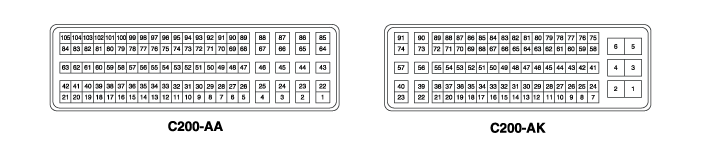
ECM Terminal Function (A/T)
Connector [C200-AA]| Pin No. | Description | Connected To |
| 1 | Injector (Cylinder No. 1) [High] Control Output | Injector (Cylinder No. 1) |
| 2 | Injector (Cylinder No. 4) [High] Control Output | Injector (Cylinder No. 4) |
| 3 | Injector (Cylinder No. 2) [High] Control Output | Injector (Cylinder #2) |
| 4 | Injector (Cylinder No. 3) [High] Control Output | Injector (Cylinder #3) |
| 5 | - | X |
| 6 | - | X |
| 7 | Purge Control Solenoid Valve (PCSV) Control Output | Purge Control Solenoid Valve (PCSV) |
| 8 | - | |
| 9 | - | X |
| 10 | Cruise Control Power Switch | Cruise control switch |
| 11 | Sensor Power Supply (+5V) | Manifold Absolute Pressure Sensor (MAPS) |
| Fuel Tank Pressure Sensor (FTPS) | ||
| 12 | Throttle Position Sensor (TPS) 1 Signal Input | Throttle Position Sensor (TPS) 1 |
| 13 | Sensor Ground | Engine Coolant Temperature Sensor (ECTS) |
| 14 | - | X |
| 15 | Sensor Power Supply (+5V) | Accelerator Pedal Position Sensor (APS) 2 |
| 16 | - | |
| 17 | - | X |
| 18 | Sensor Power Supply (+5V) | Throttle Position Sensor (TPS) 1,2 |
| 19 | Sensor Power Supply (+5V) | Accelerator Pedal Position Sensor (APS) 1 |
| 20 | Cruise Control Switch Ground | Cruise control switch |
| 21 | - | X |
| 22 | - | X |
| 23 | - | X |
| 24 | Heated Oxygen Sensor [Bank 1/Sensor 1] Heater Control Output | Heated Oxygen Sensor (HO2S) [Bank 1/Sensor 1] |
| 25 | Heated Oxygen Sensor [Bank 1/Sensor 2] Heater Control Output | Heated Oxygen Sensor [Bank 1/Sensor 2] |
| 26 | - | X |
| 27 | - | X |
| 28 | - | X |
| 29 | - | X |
| 30 | - | |
| 31 | - | |
| 32 | Sensor Ground | Throttle Position Sensor (TPS) 1,2 |
| 33 | - | X |
| 34 | Throttle Position Sensor (TPS) 2 Signal Input | Throttle Position Sensor (TPS) 2 |
| 35 | - | X |
| 36 | - | X |
| 37 | - | X |
| 38 | - | X |
| 39 | - | X |
| 40 | - | X |
| 41 | Sensor Ground | Heated Oxygen Sensor [Bank 1/Sensor 2] |
| 42 | - | X |
| 43 | - | X |
| 44 | - | X |
| 45 | - | X |
| 46 | - | X |
| 47 | - | X |
| 48 | - | X |
| 49 | - | X |
| 50 | - | X |
| 51 | Generator PWM Signal Output | Generator |
| 52 | - | X |
| 53 | Brake Switch Signal Input | Brake Switch |
| 54 | Accelerator Pedal Position Sensor (APS) 1 Signal Input | Accelerator Pedal Position Sensor (APS) 1 |
| 55 | - | |
| 56 | Accelerator Pedal Position Sensor (APS) 2 Signal Input | Accelerator Pedal Position Sensor (APS) 2 |
| 57 | - | X |
| 58 | - | X |
| 59 | - | X |
| 60 | Sensor Ground | Knock Sensor (KS) |
| 61 | Knock Sensor (KS) Signal Input | Knock Sensor (KS) |
| 62 | Sensor Ground | Accelerator Pedal Position Sensor (APS) 1 |
| 63 | Sensor Ground | Accelerator Pedal Position Sensor (APS) 2 |
| 64 | Injector (Cylinder No. 1) [Low] Control Output | Injector (Cylinder No. 1) |
| 65 | Injector (Cylinder No. 4) [Low] Control Output | Injector (Cylinder No. 4) |
| 66 | Injector (Cylinder No. 2) [Low] Control Output | Injector (Cylinder #2) |
| 67 | Injector (Cylinder No. 3) [Low] Control Output | Injector (Cylinder #3) |
| 68 | - | X |
| 69 | - | X |
| 70 | - | X |
| 71 | - | X |
| 72 | - | X |
| 73 | - | X |
| 74 | - | X |
| 75 | - | X |
| 76 | - | X |
| 77 | Fuel Tank Pressure Sensor (FTPS) Signal Input | Fuel Tank Pressure Sensor (FTPS) |
| 78 | Fuel Level Sensor (FLS) Signal Input | Fuel Level Sensor (FLS) |
| 79 | Cruise Control Switch Signal | Cruise control switch |
| 80 | - | X |
| 81 | - | |
| 82 | Engine Coolant Temperature Sensor (ECTS) Signal Input | Engine Coolant Temperature Sensor (ECTS) |
| 83 | VS-/IP- (Common Ground for VS, IP) | Heated Oxygen Sensor (HO2S) [Bank 1/Sensor 1] |
| 84 | VS+ (Nernst Cell Voltage) | Heated Oxygen Sensor (HO2S) [Bank 1/Sensor 1] |
| 85 | Fuel Pressure Control Valve (FPCV) [Low] Control Output | Fuel Pressure Control Valve (FPCV) |
| 86 | Fuel Pressure Control Valve (FPCV) [High] Control Output | Fuel Pressure Control Valve (FPCV) |
| 87 | - | X |
| 88 | - | X |
| 89 | - | X |
| 90 | - | X |
| 91 | - | X |
| 92 | - | X |
| 93 | - | X |
| 94 | - | X |
| 95 | - | X |
| 96 | - | X |
| 97 | - | X |
| 98 | - | X |
| 99 | - | X |
| 100 | - | X |
| 101 | - | X |
| 102 | - | X |
| 103 | Heated Oxygen Sensor Input Signal [Bank 1/Sensor 2] | Heated Oxygen Sensor [Bank 1/Sensor 2] |
| 104 | Rc/Rp (Pump Cell Voltage) | Heated Oxygen Sensor (HO2S) [Bank 1/Sensor 1] |
| 105 | Rc (Compensation Resistance) | Heated Oxygen Sensor (HO2S) [Bank 1/Sensor 1] |
Connector [C200-AK]
| Pin No. | Description | Connected To |
| 1 | ECM Ground | Ground |
| 2 | ECM Ground | Ground |
| 3 | Battery Power (B+) | Ignition Lock |
| 4 | ECM Ground | Ground |
| 5 | Battery Power (B+) | Ignition Lock |
| 6 | Battery Power (B+) | Main Relay |
| 7 | Sensor Ground | Camshaft Position Sensor (CMPS) [Bank 1 / Exhaust] |
| 8 | Sensor Ground | Manifold Absolute Pressure Sensor (MAPS) |
| 9 | - | X |
| 10 | Sensor Ground | Rail Pressure Sensor (RPS) |
| 11 | - | X |
| 12 | - | X |
| 13 | Sensor Power Supply (+5V) | Camshaft Position Sensor (CMPS) [Bank 1 / Intake] |
| Camshaft Position Sensor (CMPS) [Bank 1 / Exhaust] | ||
| 14 | - | X |
| 15 | Sensor Power Supply (+5V) | Rail Pressure Sensor (RPS) |
| Air Conditioning Pressure Sensor (APT) | ||
| 16 | Generator COM Signal Output | Generator |
| 17 | - | X |
| 18 | - | X |
| 19 | - | X |
| 20 | Cooling Fan Relay [Low] Control Output | Cooling Fan Relay |
| 21 | - | X |
| 22 | ETC Motor [-] Control Output | ETC motor |
| 23 | ETC Motor [+] Control Output | ETC motor |
| 24 | - | X |
| 25 | Sensor Ground | Air Conditioning Pressure Sensor (APT) |
| 26 | Manifold Absolute Pressure Sensor (MAPS) Signal Input | Manifold Absolute Pressure Sensor (MAPS) |
| 27 | Rail Pressure Sensor (RPS) Signal Input | Rail Pressure Sensor (RPS) |
| 28 | Intake Air Temperature Sensor (IATS) Signal Input | Intake Air Temperature Sensor (IATS) |
| 29 | - | |
| 30 | - | |
| 31 | - | X |
| 32 | - | X |
| 33 | - | X |
| 34 | - | X |
| 35 | - | X |
| 36 | Cooling Fan Relay [High] Control Output | Cooling Fan Relay |
| 37 | Canister Closure Valve (CCV) Control Output (without Immobilizer) | Canister Close Valve (CCV) |
| Fuel Pump Relay Control Output (with Immobilizer) | Fuel Pump Relay | |
| 38 | - | X |
| 39 | CVVT Oil Control Valve (OCV) Control Output [Bank 1/Exhaust] | CVVT Oil Control Valve (OCV) [Bank 1/Exhaust] |
| 40 | Ignition Coil Control Output (Cylinder #2) | Ignition Coil (Cylinder No. 2) |
| 41 | - | |
| 42 | Sensor Ground | Fuel Tank Pressure Sensor (FTPS) |
| 43 | - | X |
| 44 | Air Conditioning Pressure Sensor (APT) Signal Input | Air Conditioning Pressure Sensor (APT) |
| 45 | - | X |
| 46 | Stop Lamp Switch Input Signal | Brake Switch |
| 47 | Camshaft Position Sensor (CMPS) [Bank 1 / Exhaust] Input Signal | Camshaft Position Sensor (CMPS) [Bank 1 / Exhaust] |
| 48 | - | X |
| 49 | Wiper Input | Wiper Switch |
| 50 | Main Relay Control Output | Main Relay |
| 51 | Fuel Pump Relay Control Output (without Immobilizer) | Fuel Pump Relay |
| Canister Closure Valve (CCV) Control Output (with Immobilizer) | Canister Close Valve (CCV) | |
| 52 | - | X |
| 53 | - | X |
| 54 | Immobilizer Lamp Control Output | Cluster |
| 55 | - | X |
| 56 | CVVT Oil Control Valve (OCV) [Bank 1/Intake] Control Output | CVVT Oil Control Valve (OCV) [Bank 1/Intake] |
| 57 | Ignition Coil Control Output (Cylinder No. 1) | Ignition Coil (Cylinder No. 1) |
| 58 | - | X |
| 59 | CCP-CAN [High] | Other Control Module, Data Link Connector (DLC), Multi-Purpose Check Connector |
| 60 | CAN [High] | Other Control Module, Data Link Connector (DLC), Multi-Purpose Check Connector |
| 61 | Immobilizer Communication Line | Smart Key Control Module [with Engine Start Button] |
| Immobilizer Control Module [without Engine Start Button] | ||
| 62 | LIN Communication Input Signal | Battery Sensor |
| 63 | - | |
| 64 | Vehicle Speed Signal Input | Vehicle speed sensor |
| 65 | - | X |
| 66 | Camshaft Position Sensor (CMPS) [Bank 1/Intake] Signal Input | Camshaft Position Sensor (CMPS) [Bank 1 / Intake] |
| 67 | Start Signal Input | PDM Module |
| 68 | Ignition Switch Input Signal | Ignition Lock |
| 69 | - | X |
| 70 | - | X |
| 71 | Starter Relay Control Output | Starter Relay |
| 72 | - | X |
| 73 | - | X |
| 74 | Ignition Coil Control Output (Cylinder No. 4) | Ignition Coil (Cylinder No. 4) |
| 75 | Battery Power (B+) | Main Relay |
| 76 | CCP-CAN [Low] | Other Control Module, Data Link Connector (DLC), Universal Check Connector x |
| 77 | CAN [Low] | Other Control Module, Data Link Connector (DLC), Multi-Purpose Check Connector |
| 78 | Sensor Ground | Crankshaft Position Sensor (CKPS) |
| 79 | Crankshaft Position Sensor (CKPS) Input Signal [A] | Crankshaft Position Sensor (CKPS) |
| 80 | Sensor Ground | Camshaft Position Sensor (CMPS) [Bank 1 / Intake] |
| 81 | - | |
| 82 | - | |
| 83 | A/C Compressor Relay Control Output | A/C Compressor Relay |
| 84 | - | X |
| 85 | Variable Intake Solenoid (VIS) Valve Control Output | Variable Intake Solenoid (VIS) |
| 86 | - | X |
| 87 | - | X |
| 88 | Malfunction Indicator Lamp (MIL) Control Output | Malfunction Indicator Lamp (MIL) |
| 89 | - | X |
| 90 | - | X |
| 91 | Ignition Coil Control Output (Cylinder #3) | Ignition Coil (Cylinder No. 3) |
ECM Terminal Input/Output Signal (A/T)
Connector [C200-AA]| Pin No. | Description | Condition | Type | Level |
| 1 | Injector (Cylinder No. 1) [High] Control Output | Relay ON/OFF | DC Voltage | 71 V |
| 2 | Injector (Cylinder No. 4) [High] Control Output | Relay ON/OFF | DC Voltage | 71 V |
| 3 | Injector (Cylinder No. 2) [High] Control Output | Relay ON/OFF | DC Voltage | 71 V |
| 4 | Injector (Cylinder No. 3) [High] Control Output | Relay ON/OFF | DC Voltage | 71 V |
| 5 | - | X | X | X |
| 6 | - | X | X | X |
| 7 | Purge Control Solenoid Valve (PCSV) Control Output | Relay OFF | DC Voltage | Battery Voltage |
| Relay ON | Max. 1.76 V | |||
| 8 | - | |||
| 9 | - | X | X | X |
| 10 | Cruise Control Power Switch | X | X | X |
| 11 | Sensor Power Supply (+5V) | IG OFF | DC Voltage | Max. 0.5 V |
| IGNITION ON | 4.9 - 5.1 V | |||
| 12 | Throttle Position Sensor (TPS) 1 Signal Input | Idle | Analog | 0.33 ~ 4.72 V |
| 13 | Sensor Ground | Idle | DC Voltage | Max. 50 mV |
| 14 | - | X | X | X |
| 15 | Sensor Power Supply (+5V) | IG OFF | DC Voltage | Max. 0.5 V |
| IGNITION ON | 4.9 - 5.1 V | |||
| 16 | - | |||
| 17 | - | X | X | X |
| 18 | Sensor Power Supply (+5V) | IG OFF | DC Voltage | Max. 0.5 V |
| IGNITION ON | 4.9 - 5.1 V | |||
| 19 | Sensor Power Supply (+5V) | IG OFF | DC Voltage | Max. 0.5 V |
| IGNITION ON | 4.9 - 5.1 V | |||
| 20 | Cruise Control Switch Ground | |||
| 21 | - | X | X | X |
| 22 | - | X | X | X |
| 23 | - | X | X | X |
| 24 | Heated Oxygen Sensor (HO2S) [Bank 1 / Sensor 1] Heater Control Output | Relay OFF | DC Voltage | Battery Voltage |
| Relay ON | Max. 1.65 V | |||
| 25 | Heated Oxygen Sensor (HO2S) [Bank 1 / Sensor 2] Heater Control Output | Relay OFF | DC Voltage | Battery Voltage |
| Relay ON | Max. 1.65 V | |||
| 26 | - | X | X | X |
| 27 | - | X | X | X |
| 28 | - | X | X | X |
| 29 | - | X | X | X |
| 30 | - | |||
| 31 | - | |||
| 32 | Sensor Ground | Idle | DC Voltage | Max. 50 mV |
| 33 | - | X | X | X |
| 34 | Throttle Position Sensor (TPS) 2 Signal Input | Idle | Analog | 0.55 ~ 4.37 V |
| 35 | - | X | X | X |
| 36 | - | X | X | X |
| 37 | - | X | X | X |
| 38 | - | X | X | X |
| 39 | - | X | X | X |
| 40 | - | X | X | X |
| 41 | Sensor Ground | Idle | DC Voltage | Max. 50 mV |
| 42 | - | X | X | X |
| 43 | - | X | X | X |
| 44 | - | X | X | X |
| 45 | - | X | X | X |
| 46 | - | X | X | X |
| 47 | - | X | X | X |
| 48 | - | X | X | X |
| 49 | - | X | X | X |
| 50 | - | X | X | X |
| 51 | Generator PWM Signal Output | Idle | Pulse | High: Battery voltage |
| Low: Max. 1.5 V | ||||
| 52 | - | X | X | X |
| 53 | Brake Switch Signal Input | ON | DC Voltage | Battery Voltage |
| OFF | Max. 2.25 V | |||
| 54 | Accelerator Pedal Position Sensor (APS) 1 Signal Input | Idle | Analog | 0.674 ~ 4.379 V |
| 55 | - | |||
| 56 | Accelerator Pedal Position Sensor (APS) 2 Signal Input | Idle | Analog | 0.261 ~ 2.204 V |
| 57 | - | X | X | X |
| 58 | - | X | X | X |
| 59 | - | X | X | X |
| 60 | Sensor Ground | Knock | Variable | X |
| Normal | Frequency | X | ||
| 61 | Knock Sensor (KS) Signal Input | Knock | Variable | X |
| Normal | Frequency | X | ||
| 62 | Sensor Ground | Idle | DC Voltage | Max. 50 mV |
| 63 | Sensor Ground | Idle | DC Voltage | Max. 50 mV |
| 64 | Injector (Cylinder No. 1) [Low] Control Output | Relay OFF | DC Voltage | 71 V |
| Relay ON | Max. 1.0 V | |||
| 65 | Injector (Cylinder No. 4) [Low] Control Output | Relay OFF | DC Voltage | 71 V |
| Relay ON | Max. 1.0 V | |||
| 66 | Injector (Cylinder No. 2) [Low] Control Output | Relay OFF | DC Voltage | 71 V |
| Relay ON | Max. 1.0 V | |||
| 67 | Injector (Cylinder No. 3) [Low] Control Output | Relay OFF | DC Voltage | 71 V |
| Relay ON | Max. 1.0 V | |||
| 68 | - | X | X | X |
| 69 | - | X | X | X |
| 70 | - | X | X | X |
| 71 | - | X | X | X |
| 72 | - | X | X | X |
| 73 | - | X | X | X |
| 74 | - | X | X | X |
| 75 | - | X | X | X |
| 76 | - | X | X | X |
| 77 | Fuel Tank Pressure Sensor (FTPS) Signal Input | Idle | Analog | 0.3343 ~ 0.4667 V |
| 78 | Fuel Level Input Signal | Idle | Analog | 0.193 ~ 4.0 V |
| 79 | Cruise Control Switch Signal | X | X | X |
| 80 | - | X | X | X |
| 81 | - | |||
| 82 | Engine Coolant Temperature Sensor (ECTS) Signal Input | Idle | Analog | 0.270 ~ 4.77 V |
| 83 | VS-/IP- (Common Ground for VS, IP) | Idle | DC Voltage | Max. 50 mV |
| 84 | VS+ (Nernst Cell Voltage) | Idle | Analog | 0 ~ 5.1 V |
| 85 | Fuel Pressure Control Valve (FPCV) [Low] Control Output | Relay OFF | DC Voltage | 16 V |
| Relay ON | Max. 1.0 V | |||
| 86 | Fuel Pressure Control Valve (FPCV) [High] Control Output | Relay ON/OFF | DC Voltage | 16 V |
| 87 | - | X | X | X |
| 88 | - | X | X | X |
| 89 | - | X | X | X |
| 90 | - | X | X | X |
| 91 | - | X | X | X |
| 92 | - | X | X | X |
| 93 | - | X | X | X |
| 94 | - | X | X | X |
| 95 | - | X | X | X |
| 96 | - | X | X | X |
| 97 | - | X | X | X |
| 98 | - | X | X | X |
| 99 | - | X | X | X |
| 100 | - | X | X | X |
| 101 | - | X | X | X |
| 102 | - | X | X | X |
| 103 | Heated Oxygen Sensor (HO2S) [Bank 1 / Sensor 2] Signal Input | Engine | Analog | Rich: 0.6 ~ 1.0 V |
| Run | Ground: Max. 0.4 V | |||
| 104 | Rc/Rp (Pump Cell Voltage) | Idle | Analog | 0 ~ 5.1 V |
| 105 | Rc (Compensation Resistance) | Idle | Analog | 0 ~ 5.1 V |
Connector [C200-AK]
| Pin No. | Description | Condition | Type | Level |
| 1 | ECM Ground | Idle | DC Voltage | Max. 50 mV |
| 2 | ECM Ground | Idle | DC Voltage | Max. 50 mV |
| 3 | Battery Power (B+) | IG OFF | DC Voltage | Max. 1.0 V |
| IGNITION ON | Battery Voltage | |||
| 4 | ECM Ground | Idle | DC Voltage | Max. 50 mV |
| 5 | Battery Power (B+) | IG OFF | DC Voltage | Max. 1.0 V |
| IGNITION ON | Battery Voltage | |||
| 6 | Battery Power (B+) | IG OFF | DC Voltage | Max. 1.0 V |
| IGNITION ON | Battery Voltage | |||
| 7 | Sensor Ground | Idle | DC Voltage | Max. 50 mV |
| 8 | Sensor Ground | Idle | DC Voltage | Max. 50 mV |
| 9 | - | X | X | X |
| 10 | Sensor Ground | Idle | DC Voltage | Max. 50 mV |
| 11 | - | X | X | X |
| 12 | - | X | X | X |
| 13 | Sensor Power Supply (+5V) | IG OFF | DC Voltage | Max. 0.5 V |
| IGNITION ON | 4.9 - 5.1 V | |||
| 14 | - | X | X | X |
| 15 | Sensor Power Supply (+5V) | IG OFF | DC Voltage | Max. 0.5 V |
| IGNITION ON | 4.9 - 5.1 V | |||
| 16 | Generator COM Signal Output | Idle | Pulse | High: Battery voltage |
| Low: Max. 0.6 V | ||||
| 17 | - | X | X | X |
| 18 | - | X | X | X |
| 19 | - | X | X | X |
| 20 | Cooling Fan Relay [Low] Control Output | Relay OFF | DC Voltage | Battery Voltage |
| Relay ON | Max. 1.76 V | |||
| 21 | - | X | X | X |
| 22 | ETC Motor [-] Control Output | Idle | Pulse | High: Battery voltage |
| Low: Max. 1.0 V | ||||
| 23 | ETC Motor [+] Control Output | Idle | Pulse | High: Battery voltage |
| Low: Max. 1.0 V | ||||
| 24 | - | X | X | X |
| 25 | Sensor Ground | Idle | DC Voltage | Max. 50 mV |
| 26 | Manifold Absolute Pressure Sensor (MAPS) Signal Input | Idle | Analog | 0.6683 ~ 4.346 V |
| 27 | Rail Pressure Sensor (RPS) Signal Input | Idle | Analog | 0.43 ~ 3.46 V |
| 28 | Intake Air Temperature Sensor (IATS) Input Signal | Idle | Analog | 0.209 ~ 4.756 V |
| 29 | - | |||
| 30 | - | |||
| 31 | - | X | X | X |
| 32 | - | X | X | X |
| 33 | - | X | X | X |
| 34 | - | X | X | X |
| 35 | - | X | X | X |
| 36 | Cooling Fan Relay [High] Control Output | Relay OFF | DC Voltage | Battery Voltage |
| Relay ON | Max. 1.76 V | |||
| 37 | Canister Closure Valve (CCV) Control Output (without Immobilizer) | Active | DC Voltage | Battery Voltage |
| Inactive | Max. 1.76 V | |||
| Fuel Pump Relay Control Output (with Immobilizer) | Relay OFF | DC Voltage | Battery Voltage | |
| Relay ON | Max. 1.44 V | |||
| 38 | - | X | X | X |
| 39 | CVVT Oil Control Valve (OCV) Control Output [Bank 1/Exhaust] | Idle | Pulse | High: Battery voltage |
| Low: Max. 1.65 V | ||||
| 40 | Ignition Coil Control Output (Cylinder #2) | Idle | Pulse | 1st Voltage: 370 ~ 430 V |
| ON Voltage: 2.2 V Max. | ||||
| 41 | - | X | X | X |
| 42 | Sensor Ground | Idle | DC Voltage | Max. 50 mV |
| 43 | - | X | X | X |
| 44 | Air Conditioning Pressure Sensor (APT) Signal Input | A/C ON | Analog | 0.348 ~ 4.63 V |
| 45 | - | X | X | X |
| 46 | Stop Lamp Switch Input Signal | ON | DC Voltage | Battery Voltage |
| OFF | Max. 2.25 V | |||
| 47 | Camshaft Position Sensor (CMPS) [Bank 1 / Exhaust] Input Signal | Idle | Pulse | High: Min. 4.8 V |
| Low: Max. 0.6 V | ||||
| 48 | - | X | X | X |
| 49 | Wiper Input | |||
| 50 | Main Relay Control Output | Relay OFF | DC Voltage | Battery Voltage |
| Relay ON | Max. 1.7 V | |||
| 51 | Canister Closure Valve (CCV) Control Output (with Immobilizer) | Active | DC Voltage | Battery Voltage |
| Inactive | Max. 1.76 V | |||
| Fuel Pump Relay Control Output (without Immobilizer) | Relay OFF | DC Voltage | Battery Voltage | |
| Relay ON | Max. 1.44 V | |||
| 52 | - | X | X | X |
| 53 | - | X | X | X |
| 54 | Immobilizer Lamp Control Output | X | X | X |
| 55 | - | X | X | X |
| 56 | CVVT Oil Control Valve (OCV) [Bank 1/Intake] Control Output | Idle | Pulse | High: Battery voltage |
| Low: Max. 1.65 V | ||||
| 57 | Ignition Coil Control Output (Cylinder No. 1) | Idle | Pulse | 1st Voltage: 370 ~ 430 V |
| ON Voltage: 2.2 V Max. | ||||
| 58 | - | X | X | X |
| 59 | CCP-CAN [High] | RECESSIVE | Pulse | 2.0 - 3.0 V |
| DOMINANT | 2.75 - 4.5 V | |||
| 60 | CAN [High] | RECESSIVE | Pulse | 2.0 - 3.0 V |
| DOMINANT | 2.75 - 4.5 V | |||
| 61 | Immobilizer Communication Line | During transmission | Pulse | High: Min. 8.4 V (at 14 V) |
| Low: Max. 6.44 V (at 14 V) | ||||
| 62 | LIN Communication Input Signal | RECESSIVE | Pulse | Max. 5.6 V (at 14 V) |
| DOMINANT | Min. 8.4 V (at 14 V) | |||
| 63 | - | |||
| 64 | Vehicle Speed Signal Input | Idle | Pulse | High: Min. 5.4 V |
| Low: Max. 2.25 V | ||||
| 65 | - | X | X | X |
| 66 | Camshaft Position Sensor (CMPS) [Bank 1/Intake] Signal Input | Idle | Pulse | High: Min. 4.8 V |
| Low: Max. 0.6 V | ||||
| 67 | Start Signal Input | ON | DC Voltage | Battery Voltage |
| OFF | Max. 2 V | |||
| 68 | Ignition Switch Input Signal | IG OFF | DC Voltage | Max. 1.0 V |
| IGNITION ON | Battery Voltage | |||
| 69 | - | X | X | X |
| 70 | - | X | X | X |
| X | X | |||
| 71 | Starter Relay Control Output | Relay OFF | DC Voltage | Battery Voltage |
| Relay ON | Max. 2.64 V | |||
| 72 | - | X | X | X |
| 73 | - | X | X | X |
| 74 | Ignition Coil Control Output (Cylinder No. 4) | Idle | Pulse | 1st Voltage: 370 ~ 430 V |
| ON Voltage: 2.2 V Max. | ||||
| 75 | Battery Power (B+) | IG OFF | DC Voltage | Max. 1.0 V |
| IGNITION ON | Battery Voltage | |||
| 76 | CCP-CAN [Low] | RECESSIVE | Pulse | 2.0 - 3.0 V |
| DOMINANT | 0.5 - 2.25 V | |||
| 77 | CAN [Low] | RECESSIVE | Pulse | 2.0 - 3.0 V |
| DOMINANT | 0.5 - 2.25 V | |||
| 78 | Sensor Ground | Idle | DC Voltage | Max. 50 mV |
| 79 | Crankshaft Position Sensor (CKPS) Input Signal [A] | Idle | Pulse | Vp_p: Min. 1.0 V |
| 80 | Sensor Ground | Idle | DC Voltage | Max. 50 mV |
| 81 | - | |||
| 82 | - | |||
| 83 | A/C Compressor Relay Control Output | Relay OFF | DC Voltage | Battery Voltage |
| Relay ON | Max. 1.0 V | |||
| 84 | - | X | X | X |
| 85 | Variable Intake Solenoid (VIS) Valve Control Output | Relay OFF | DC Voltage | Battery Voltage |
| Relay ON | Max. 1.65 V | |||
| 86 | - | X | X | X |
| 87 | - | X | X | X |
| 88 | Malfunction Indicator Lamp (MIL) Control Output | X | X | X |
| 89 | - | X | X | X |
| 90 | - | X | X | X |
| 91 | Ignition Coil Control Output (Cylinder #3) | Idle | Pulse | 1st Voltage: 370 ~ 430 V |
| ON Voltage: 2.2 V Max. |
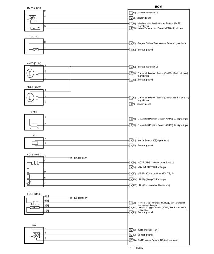
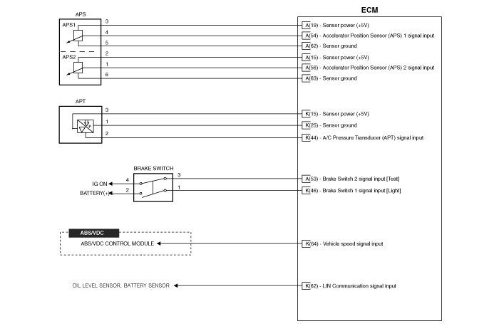
Wiring Diagram
(M/T)

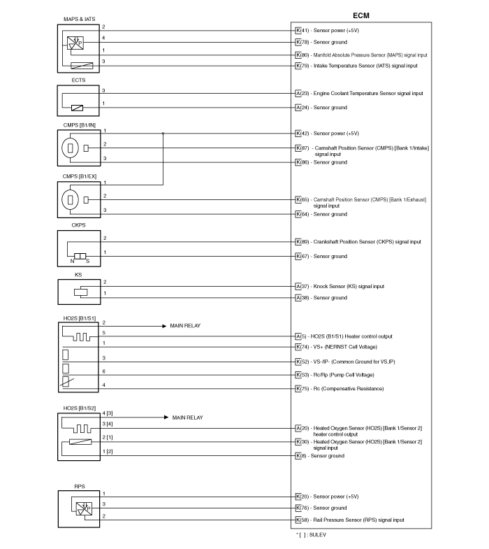
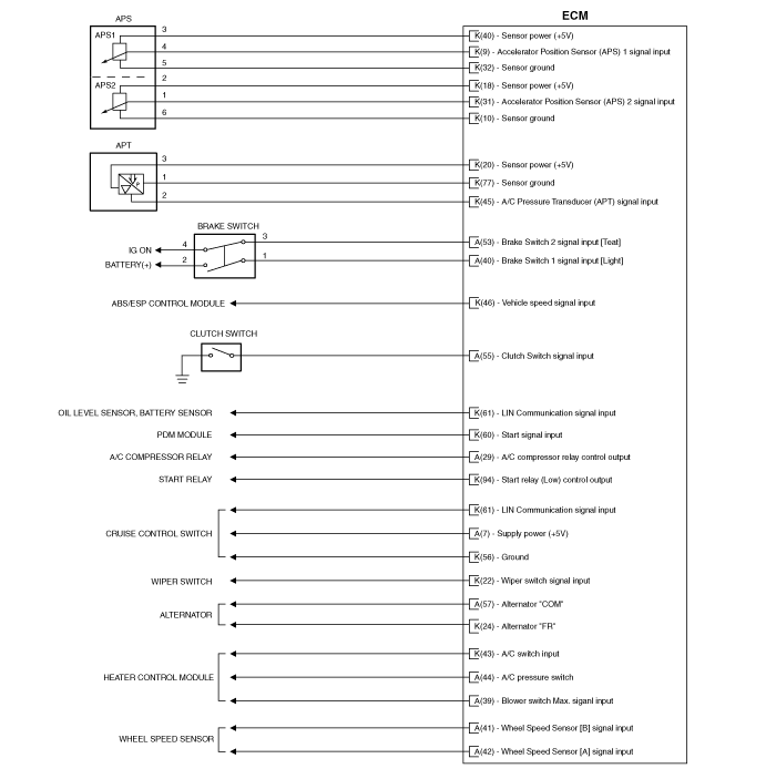
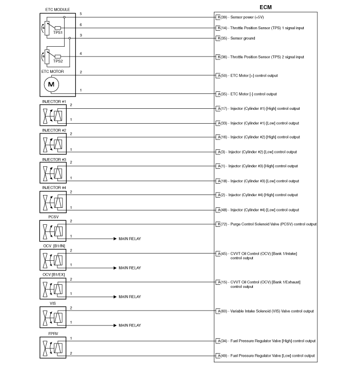
(B)


Test yourself
A quick Hyundai Tucson LM quiz: every answer comes with an explanation and a link to the manual page.
Was this page helpful?