FCA Radar
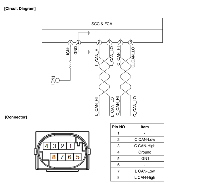
Circuit Diagrams
Wiring Diagram
Repair Procedures
Removal
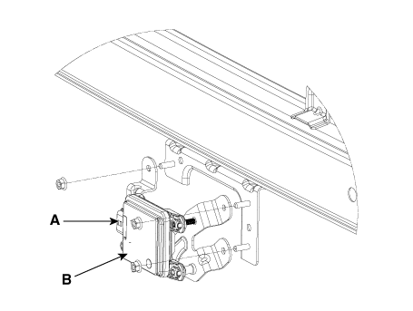
SCC and FCA Radar and Unit
Remove the front bumper.
(Refer to Body (Interior and Exterior) - "Front Bumper Cover")
Disconnect the SCC and FCA radar connector (A).
Remove the SCC and FCA radar (B) after loosening the mounting nuts.
Tightening torque: 10.17–12.2 N·m
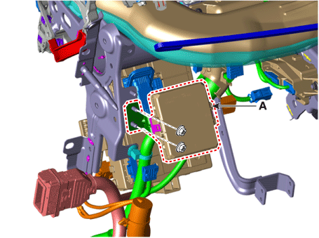
SCC and FCA Unit (Australia only)
Remove the driver airbag module assembly.
(Refer to Body (Interior and Exterior) - "Main Protector Assembly")
Disconnect the SCC and FCA unit connector.
Remove the SCC and FCA unit (A).
Tightening torque: 9.8–10.8 N·m
Installation
SCC and FCA Radar and Unit
Install in the reverse order of removal.
Align the variant coding procedure.
(Refer to Adjustment - "Variant Coding")
Align the smart cruise control radar sensor.
(Refer to Adjustment - "FCA Radar Alignment")
SCC and FCA Unit (Australia only)
Install in the reverse order of removal.
Align the variant coding procedure.
(Refer to Adjustment - "Variant Coding")
Adjustment
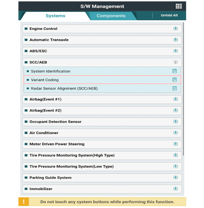
Variant Coding
Turn the ignition off.
Connect the KDS to the Data Link Connector (DLC).
Turn the ignition on.
Select "Vehicle, Model Year, Engine, System".
Select "Vehicle Software Management".
Perform variant coding.
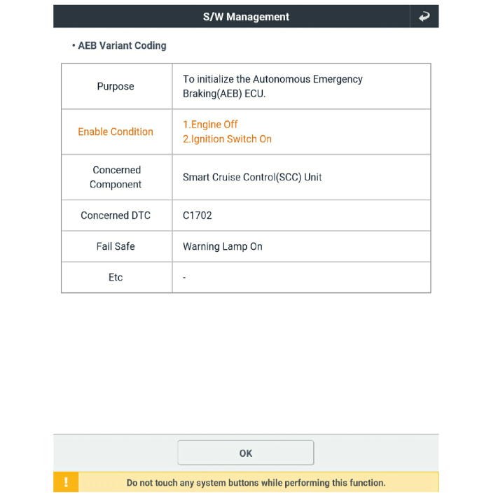
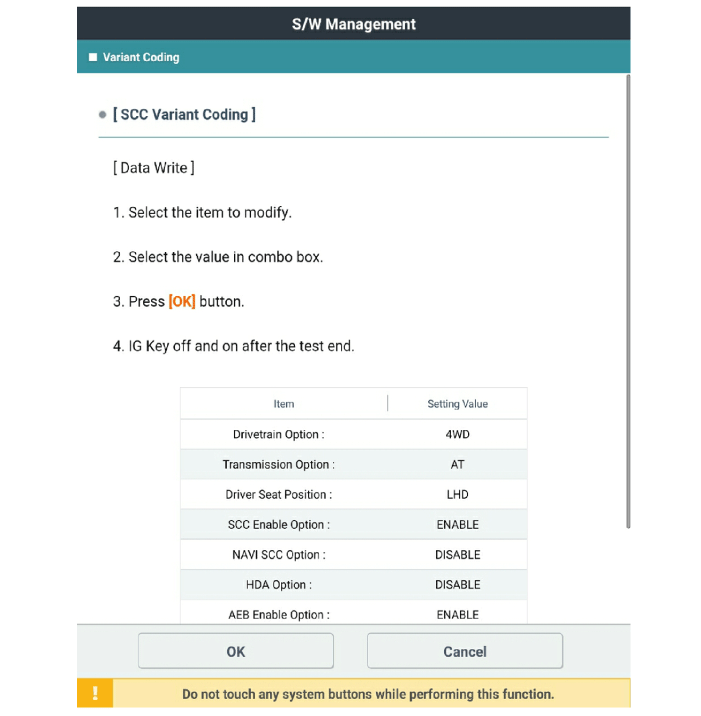
Forward Collision-Avoidance Assist (FCA) Radar Alignment
The Forward Collision-Avoidance Assist (FCA) system is designed to prevent a potential collision or reduce its impact when the driver applies the brakes inadequately, late, or not at all to avoid a collision.
For the radar sensor to operate correctly, it must be aligned correctly parallel to the vehicle's direction of travel. For this reason, the radar sensor alignment procedure must be performed each time the sensor is reinstalled or replaced with a new one.
If the sensor alignment procedure is not performed under the conditions specified above, the smart cruise control system may not operate correctly.
Forward Collision-Avoidance Assist (FCA) Radar Alignment
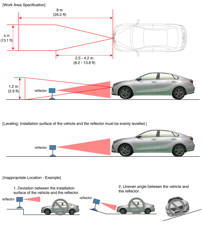
Park the vehicle horizontally on level ground.
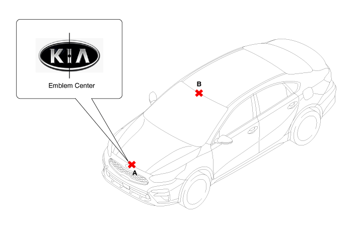
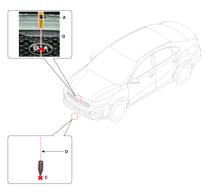
Mark the center point of the emblem (A) and the center point on the windshield glass (B).
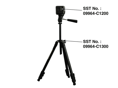
Attach the SCC calibration laser (SST No.: 09964-C1200) to the tripod (SST No.: 09964-C1300).
Using the SCC calibration reflector [SST No.: 09964-C1100] (A), adjust the wire (D) so that the center point of the emblem (B) and the center point on the ground (C) are perpendicular to each other.
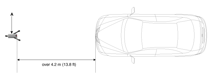
Install the vertical/horizontal laser [SST No.: 09964-C1200] (A) at a distance of more than 4.2 m (12.5 ft) from the front of the vehicle.
Align the vertical laser line with (A) and (B) using the vertical/horizontal laser (C) [SST No.: 09964-C1200].
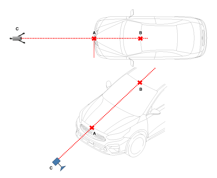
Mark (C) at a distance of 1.0–3.8 m (3.3–12.5 ft) from (A) in front of the vehicle.
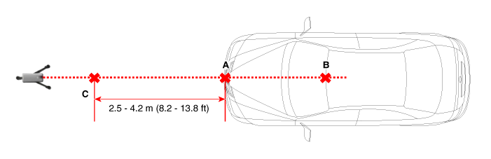
Remove the SCC calibration laser [SST No.: 09964-C1200] (B) from the tripod [SST No.: 09964-C1300] (A).
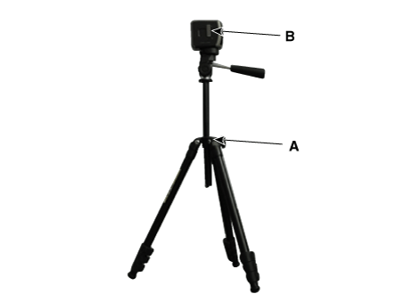
Install the reflector [SST No.: 09964-C1100] (B) on the stand [SST No.: 09964-C1300] (A).
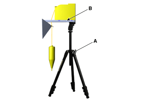
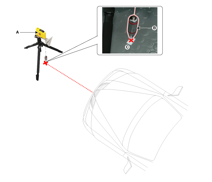
Align the vertical weight (B) of the SCC calibration reflector [SST No.: 09964-C1100] (A) with point (C).
Using the level vial (B) of the stand [SST No.: 09964-C1300] (A), set the reflector horizontally.
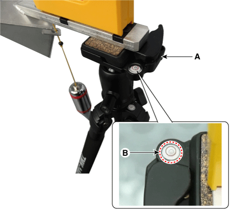
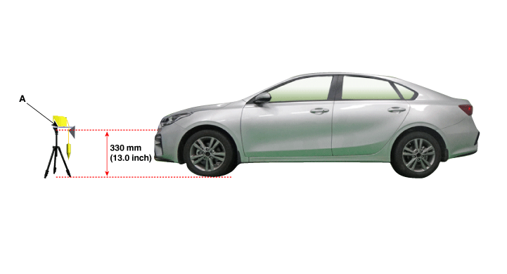
Set the height of the SCC calibration reflector [SST No.: 09964-C1100] (A) to 330 mm (13.0 in.).
Visually check the radar sensor and front bumper surface again for any objects.
Connect the KDS to the vehicle DLC and start the sensor alignment.
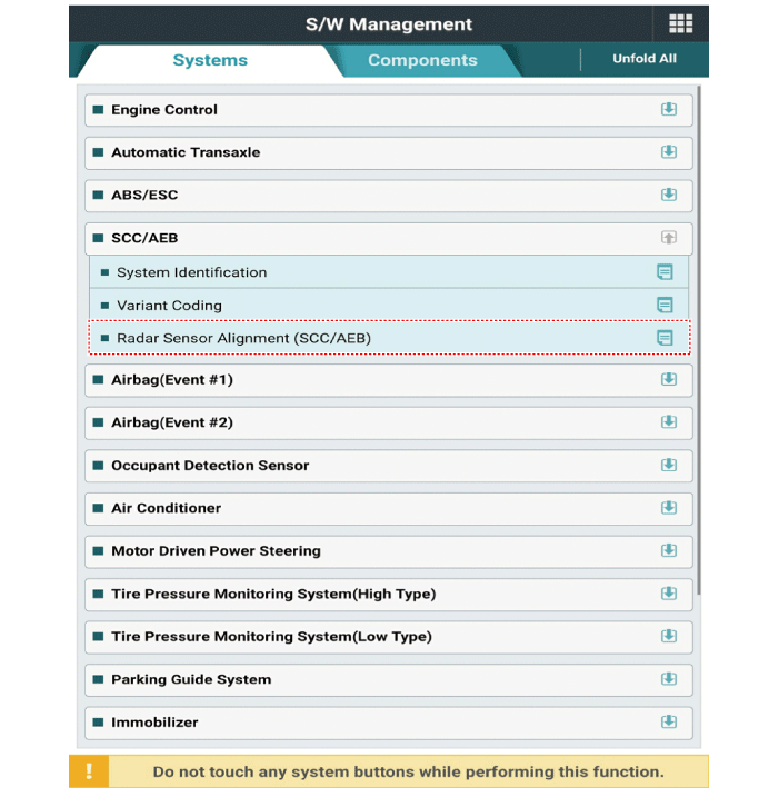
After selecting the correct vehicle model, select "Radar Sensor Alignment" from the auxiliary functions in the KDS menu.
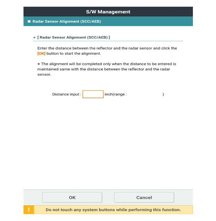
Perform the sensor alignment by following the instructions shown on the KDS monitor.
If the sensor alignment fails, check the alignment conditions. Turn the ignition off, then repeat the sensor alignment procedure.
Inspection
Forward Collision-Avoidance Assist (FCA) System Malfunction Check Procedures:
Inspect the front bumper appearance and accident history (bumper appearance, vehicle service history, and bumper replacement history).
→ If the vehicle has been involved in a collision, the FCA mounting bracket may be bent.
Check whether the radar sensor cover on the bumper is contaminated.
→ If the cover is dirty, the FCA may be obstructed by foreign substances during operation.
After starting the engine, check the FCA warning message on the instrument panel and the DTC. (Refer to the DTC chart.)
After starting the engine, stop the vehicle for more than 5 seconds.
→ If the system initialization (yaw rate sensor offset compensation) is not completed, the FCA will not operate.
Test yourself
A quick Kia Forte BD quiz: every answer comes with an explanation and a link to the manual page.