Manual transaxle
Components and Component Location
Components
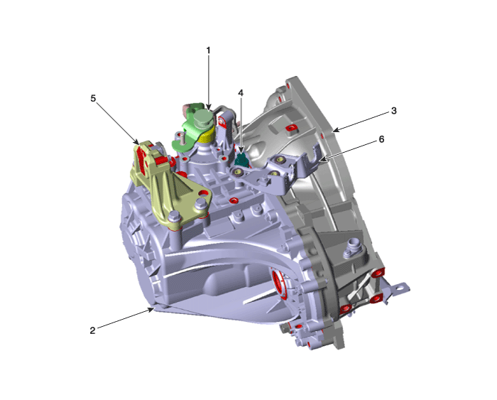
| 1. Control Shaft Assembly 2. Manual Transaxle Case 3. Clutch Housing |
4. Back-up Light Switch 5. Manual Transaxle Support Bracket 6. Control Cable Bracket |
Repair Procedures
Removal
Remove the air cleaner assembly and air duct.
(Refer to Engine Mechanical System - "Air Cleaner")
Remove the battery and battery tray.
(Refer to Engine Electrical System - Battery)
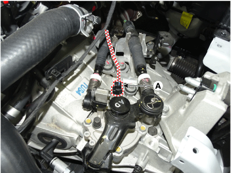
Disconnect the back-up light switch connector (A).
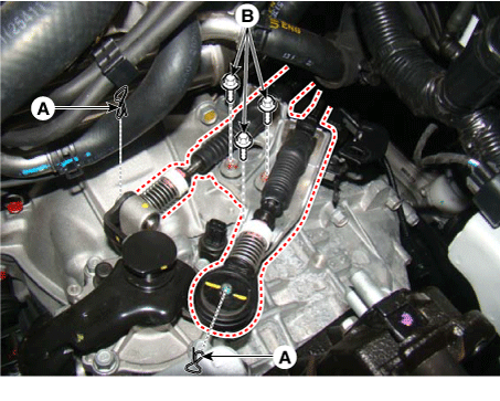
Remove the control cable.
Remove the control cable from the control shaft after removing the pins (A).
Loosen the control cable bracket bolts (B).
Tightening torque: 14.7 ~ 22 N·m
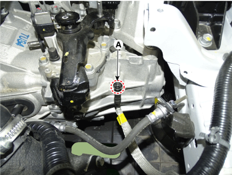
Remove the ground bolt (A).
Tightening Torque: 9.8–11.8 N·m
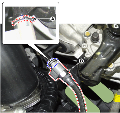
Disconnect the clutch tube (B) after removing the clip (A).
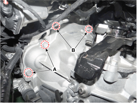
Remove the starter mounting bolt (A), then the upper transaxle mounting bolt (B).
Tightening torque:
(A) 49,0–64 N·m
(B) 42,2–54 N·m
Remove the upper hood cover.
(Refer to Body - "Upper Cowl Cover")
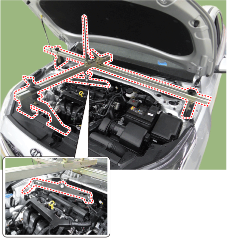
Assemble the engine mount in the engine compartment.
(Refer to Special Service Tools — "Engine Mount Assembly Drawing")
Using the engine support, hold the engine and transmission assembly securely.
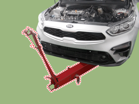
Securely support the transmission on a jack.
Remove the dust cover (A).
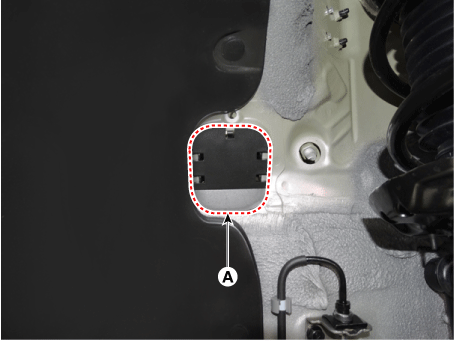
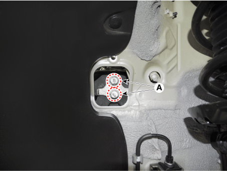
Remove the mounting bolts (A) from the transaxle support bracket.
Tightening torque: 98.1–118 N·m
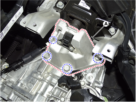
Remove the transmission support bracket (A).
Tightening torque: 58.9–78 N·m
Remove the under cover.
(Refer to Engine Mechanical System - "Engine Room Cover")
Remove the vacuum pump.
(Refer to Brake System - "Vacuum Pump")
Remove the drive shaft assembly.
(Refer to Drive Shaft and Axle — "Front Propeller Shaft")
Remove the roller rod bracket (C) after loosening the bolts (A) and (B).
Tightening torque:
(A) 49,0–64 N·m
(B) 107,9–128 N·m
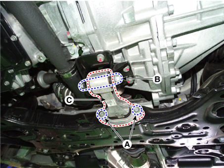
Remove the roller rod support bracket (A).
Tightening torque: 49.0–69 N·m
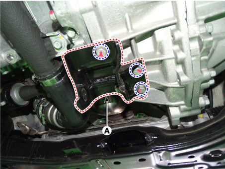
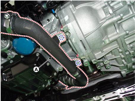
Remove the intake hose and intercooler pipe (A).
Tightening torque: 18.6–24 N·m
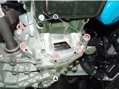
Loosen the lower mounting bolts (A, B) of the transaxle. Then remove the transaxle assembly while supporting it with a jack.
Tightening torque:
(A) 42,2–48 N·m
(B) 42,2–54 N·m
Installation
Install in the reverse order of removal.
After filling with brake fluid, perform the air bleeding procedure for the concentric slave cylinder.
(Refer to Clutch System - Concentric Slave Cylinder Assembly)
Test yourself
A quick Kia Forte BD quiz: every answer comes with an explanation and a link to the manual page.